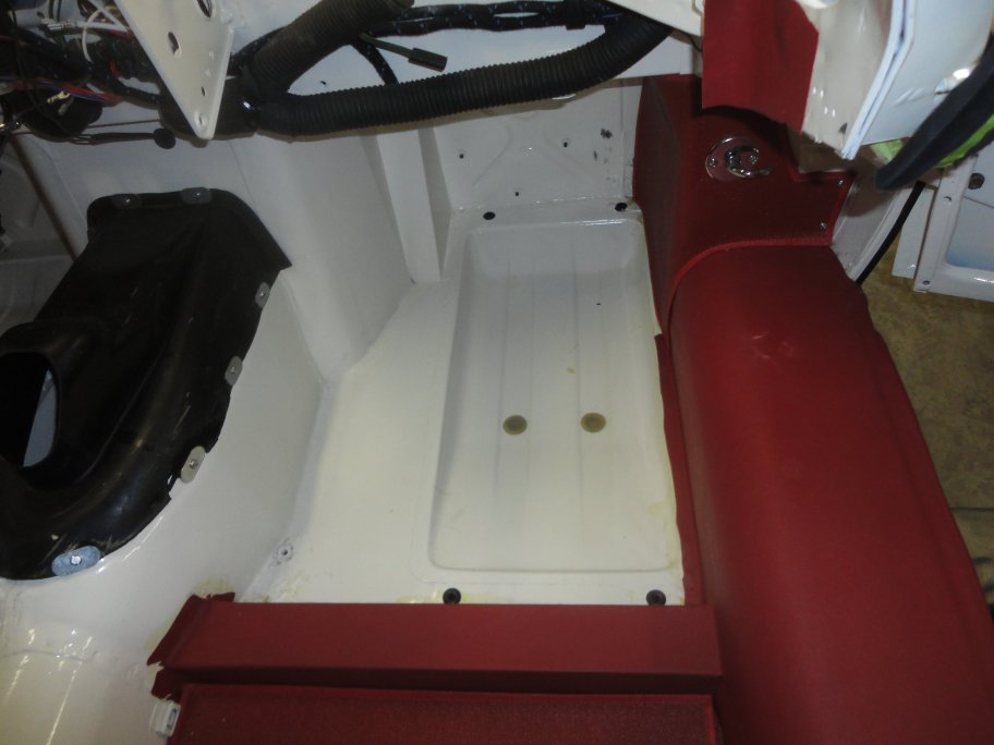
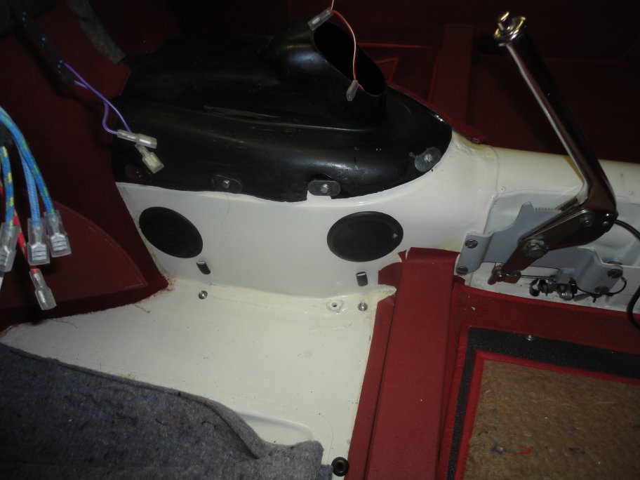
 50) Before the padding goes in, the body plugs must be installed. They do not make the original style body plugs or suitable replacements
in clear plastic. Luckily, most of the body plugs had survived the restoration process. The original plugs (2) can be seen here in the center of
the floorpan. Also seen here are the four plugs (black) for the carpet retainers. The female pieces are installed in the floorpan. When
the carpets are intalled, the mating male pieces are pushed through the carpet and snap into the female pieces.
50) Before the padding goes in, the body plugs must be installed. They do not make the original style body plugs or suitable replacements
in clear plastic. Luckily, most of the body plugs had survived the restoration process. The original plugs (2) can be seen here in the center of
the floorpan. Also seen here are the four plugs (black) for the carpet retainers. The female pieces are installed in the floorpan. When
the carpets are intalled, the mating male pieces are pushed through the carpet and snap into the female pieces.
|
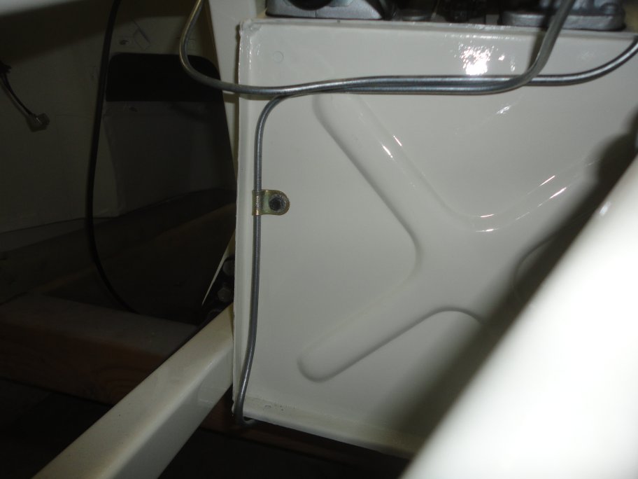 51) The front portion of the rear brake line is mounted to the front of the bulkhead with a bolt that musted be nutted from the inside
of the car. This must be done prior to glueing in the footwell padding.
51) The front portion of the rear brake line is mounted to the front of the bulkhead with a bolt that musted be nutted from the inside
of the car. This must be done prior to glueing in the footwell padding.
|
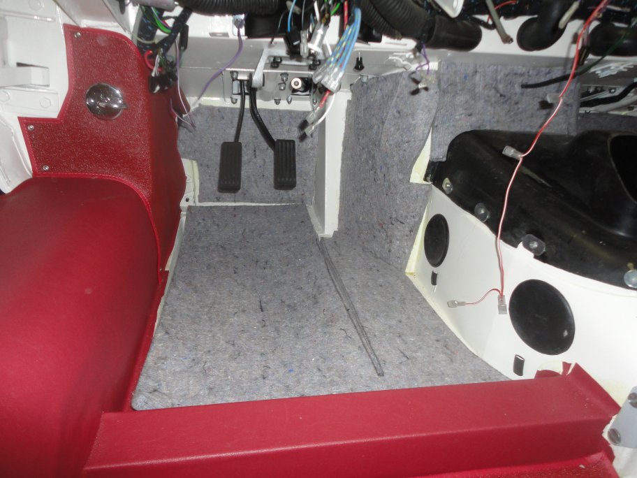 52) The jute padding is glued in using contact cement. The padding on the floor is not glued in however. As can be seen in this picture,
the jute padding is not glued to the side of the transmission tunnel on the left side of the car. This is so that the
transmission linkage can be accessed and adjusted.
52) The jute padding is glued in using contact cement. The padding on the floor is not glued in however. As can be seen in this picture,
the jute padding is not glued to the side of the transmission tunnel on the left side of the car. This is so that the
transmission linkage can be accessed and adjusted.
|
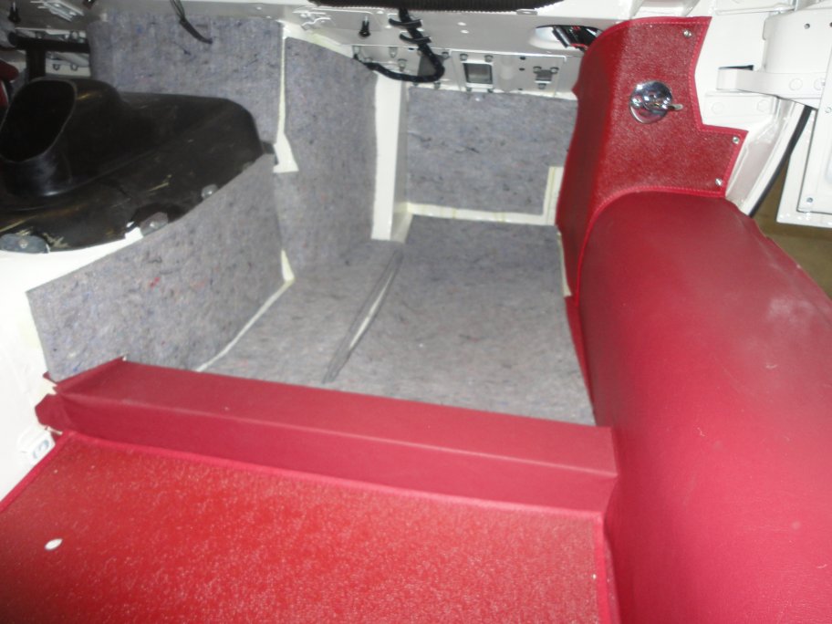 53) The pute padding is glued to the transmission tunnel on the right hand side though. It should be noted that the console is a tight fit,
so the padding should not go much higher than the transmission cover mounting screws.
53) The pute padding is glued to the transmission tunnel on the right hand side though. It should be noted that the console is a tight fit,
so the padding should not go much higher than the transmission cover mounting screws.
|
 54) Installed onto the floor below each transmission tunnel plug is a pair of snaps. These are for the removable carpet section. The snaps are either
pop-rivetted or screwed into the floorplan.
54) Installed onto the floor below each transmission tunnel plug is a pair of snaps. These are for the removable carpet section. The snaps are either
pop-rivetted or screwed into the floorplan.
|
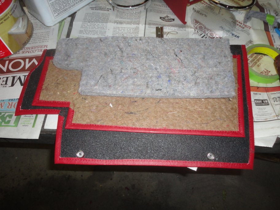 55) Here is the carpet section that is used to cover the left side of the transmission tunnel. The mating snaps can be seen at the bottom. The carpet
section has a pocket sewn into it which holds a piece of jute padding.
55) Here is the carpet section that is used to cover the left side of the transmission tunnel. The mating snaps can be seen at the bottom. The carpet
section has a pocket sewn into it which holds a piece of jute padding.
|
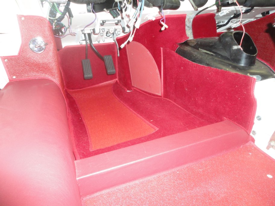 56) On the driver's side, a carpet section is glued to the jute padding at the front of the transmission tunnel and on the face of the bulkhead. Then
the transmision tunnel piece is just snapped in place. After that, the carpet for the floor is dropped in place and is only retained with the forementioned
male plastics snaps (not shown).
56) On the driver's side, a carpet section is glued to the jute padding at the front of the transmission tunnel and on the face of the bulkhead. Then
the transmision tunnel piece is just snapped in place. After that, the carpet for the floor is dropped in place and is only retained with the forementioned
male plastics snaps (not shown).
|
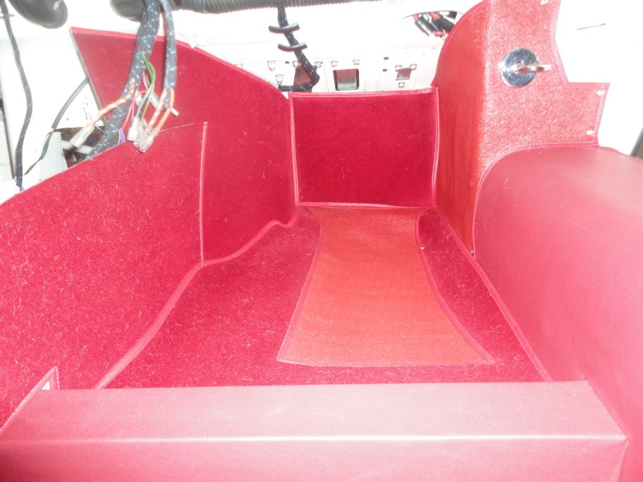 57) The right side goes together the same way as the left side with the exception of the carpet being glued to the side of the transmission tunnel.
|
|
|
|
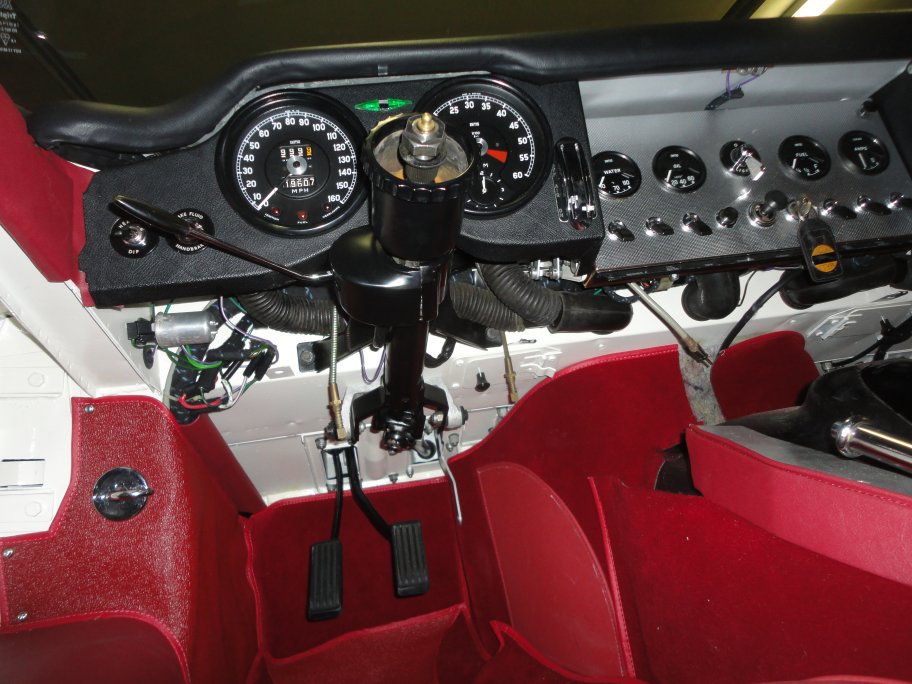
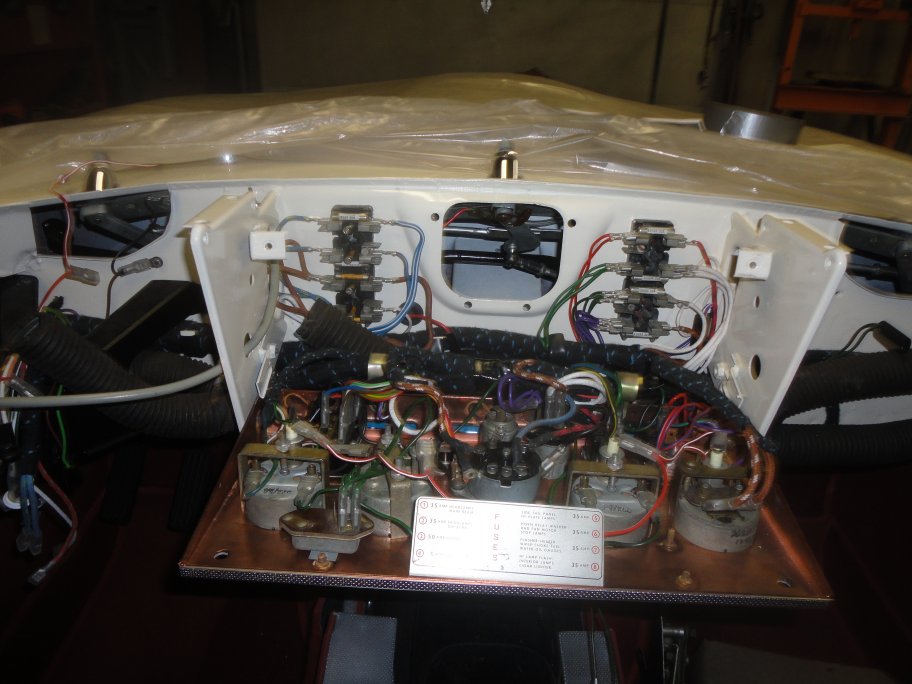 58) The dash wiring takes some patience and a good wiring diagram. Over the years the colors fade to white on the original
cloth wires, leaving just a hint as to what the colors were originally. The biggest difference I found was that the new
harness had the reverse light wire integrated into the harness, while my original one was tapped to the outside of the
harness.
58) The dash wiring takes some patience and a good wiring diagram. Over the years the colors fade to white on the original
cloth wires, leaving just a hint as to what the colors were originally. The biggest difference I found was that the new
harness had the reverse light wire integrated into the harness, while my original one was tapped to the outside of the
harness.
In this picture you can see the center gauges and fuse terminals after installation. I had the center panel plated in copper
by Paul's chrome. The gauges were cleaned and the bezels were repainted. I left the original 1962 date makings on the gauges.
|
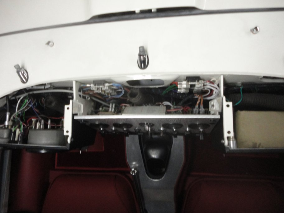 59) The center defrost duct should not be constrained when the center console is closed.
|
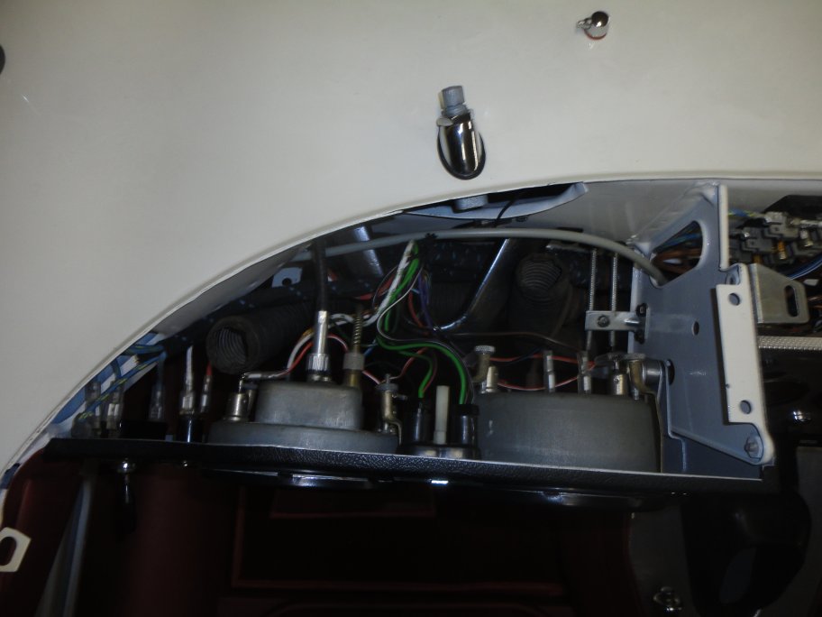 60) The main gauge cluster is simple to install. The best was to make the cluster connections and adjust the heater controls is with
the windshield out of the way and no dash pad.
60) The main gauge cluster is simple to install. The best was to make the cluster connections and adjust the heater controls is with
the windshield out of the way and no dash pad.
|
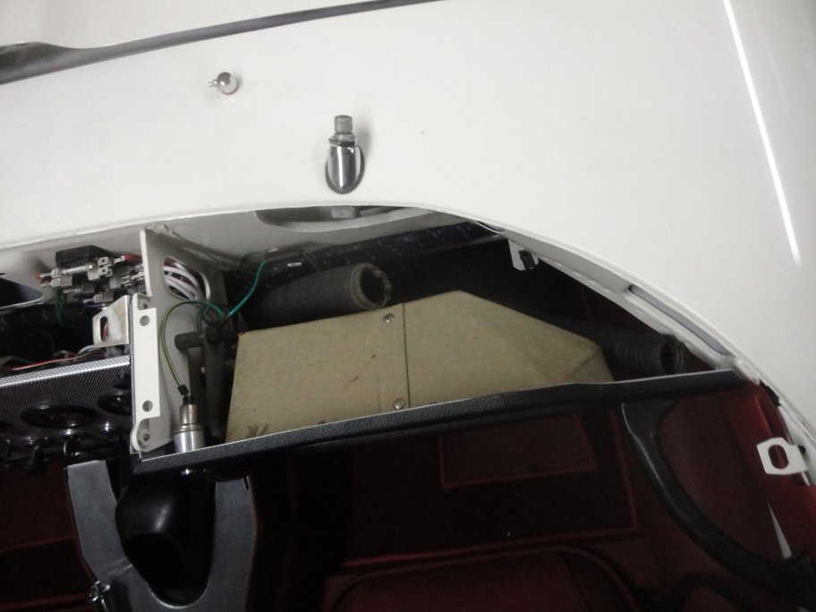 61) The glove box panel must be installed in conjuntion with the choke cable. On early E-types such as this, the grab hand must be installed prior
to the dash pad. This is becuase the handle bolts through the panel. Later on in production a chrome bracket was bolted to the panel as a base
for the grab handle.
61) The glove box panel must be installed in conjuntion with the choke cable. On early E-types such as this, the grab hand must be installed prior
to the dash pad. This is becuase the handle bolts through the panel. Later on in production a chrome bracket was bolted to the panel as a base
for the grab handle.
|
 62) Next to go on is the dash pad. In this picture the bare sheet metal frame was fitted to the dash for straightening.
|
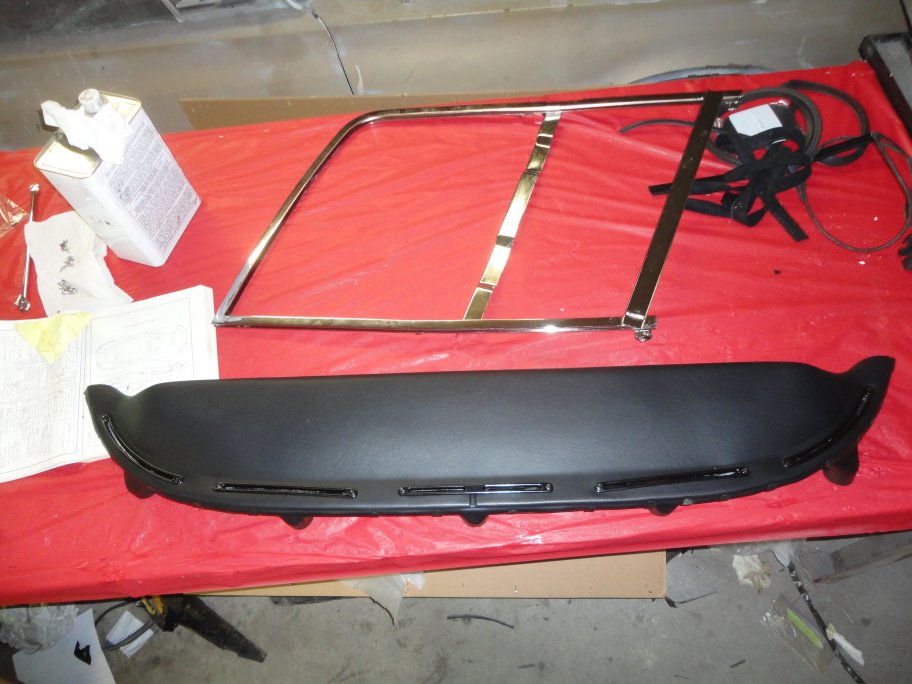 63) New dash pads are available molded with the correct contours. However, a heat gun must be employed to bend the rigid plastic around the sheet metal
frame for glueing. A significant amount of clips (18) are used to hold the pad firmly to the frame along the windshield. New clips are available
fro the usuals. They are part number BD10313.
63) New dash pads are available molded with the correct contours. However, a heat gun must be employed to bend the rigid plastic around the sheet metal
frame for glueing. A significant amount of clips (18) are used to hold the pad firmly to the frame along the windshield. New clips are available
fro the usuals. They are part number BD10313.
|
 64) The steering column is next to go in. Installation is relatively painless, but make sure you have a good diagram to plug the wires in since the
some of the wires that mate at the junction block are not of the same color.
64) The steering column is next to go in. Installation is relatively painless, but make sure you have a good diagram to plug the wires in since the
some of the wires that mate at the junction block are not of the same color.
|
|