 30) The next step in the process was the covering of the sills and the crossmembers. It is ok to do this prior to the cubby
area. However, I prefer to work form the inside out so that I do not have to work across new material which would make it dirty or potentially
damage it.
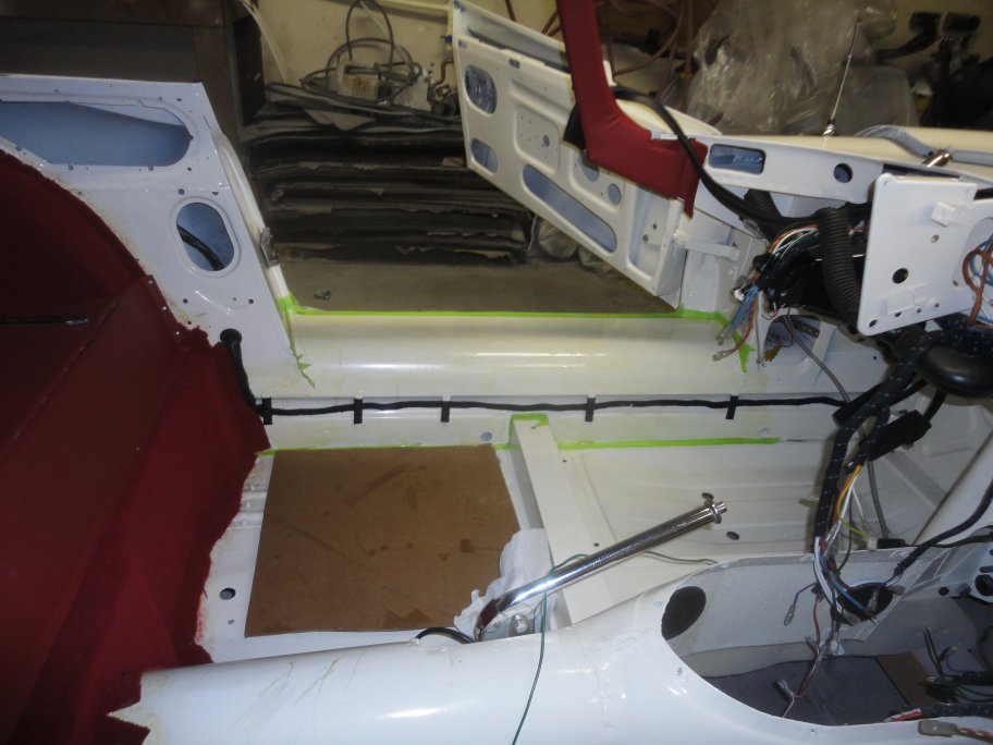
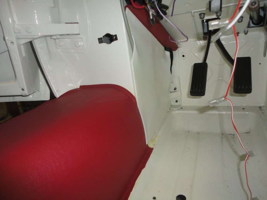
30) The next step in the process was the covering of the sills and the crossmembers. It is ok to do this prior to the cubby
area. However, I prefer to work form the inside out so that I do not have to work across new material which would make it dirty or potentially
damage it.The first step was to cover the sills with foam. As you can see in this picture, there is a cove area where the main wiring harness runs to the rear of the car. The foam covers this and allows the vinyl sill covering to remain flat, creating a cleaner look. In this picture the perimeter was masked off and a layer of contact cement was applied. Though not shown very well here it is very important to know that the outer 1/2" inch of the sill must not be covered in foam. This is because the chrome sill trim will not be able to fit over the vinyl and foam together. |
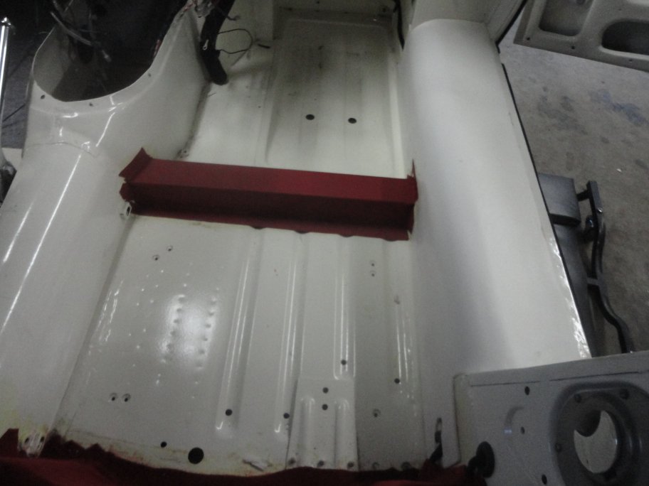
 31) The foam was then applied and trimmed back to the tapped border.
 |
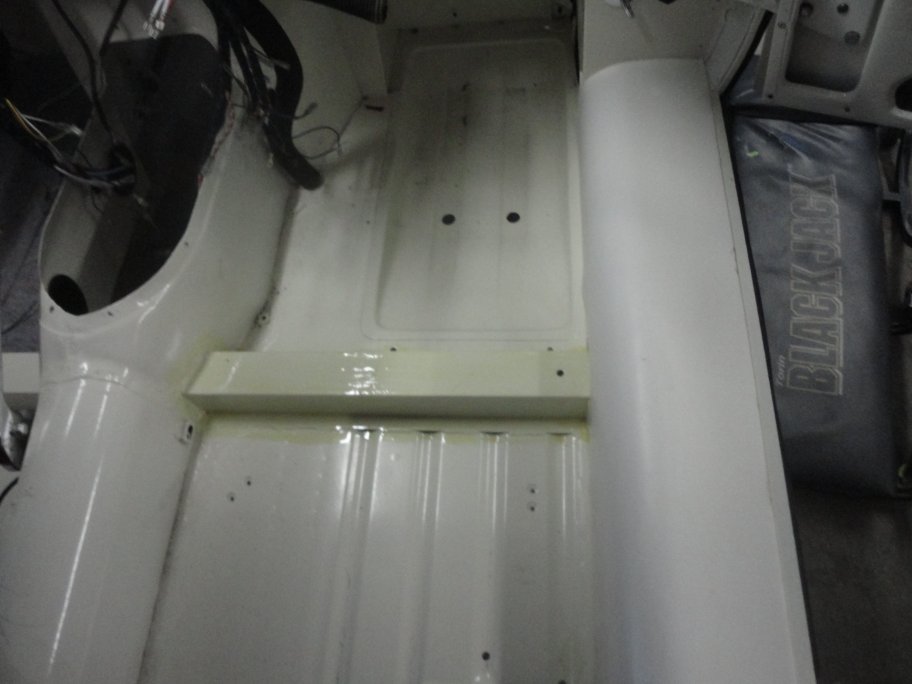 32) The crossmembers are covered in vinyl on early cars. Carpet was applied to later cars. The kit I got came with carpet, so I had to get some vinyl from them to
do the job correctly. For this area I prefered to just brush on the contact cement without masking the perimeter.
32) The crossmembers are covered in vinyl on early cars. Carpet was applied to later cars. The kit I got came with carpet, so I had to get some vinyl from them to
do the job correctly. For this area I prefered to just brush on the contact cement without masking the perimeter.Note: In this picture you can see that the foam does not extend all the way to the outside of the sill as mentioned previouisly. |
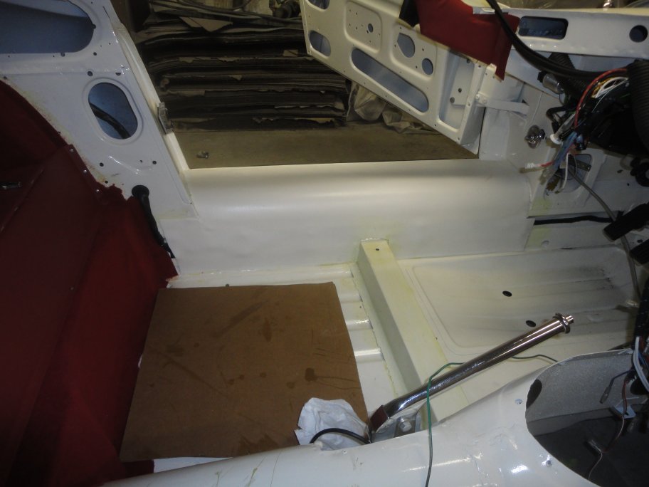
 33) The vinyl is applied with nice tight corners and should extend onto the sills, transmission tunnel and onto the floor in order to prevent body color from showing
through when the carpets and sill vinyl are installed.
33) The vinyl is applied with nice tight corners and should extend onto the sills, transmission tunnel and onto the floor in order to prevent body color from showing
through when the carpets and sill vinyl are installed. |
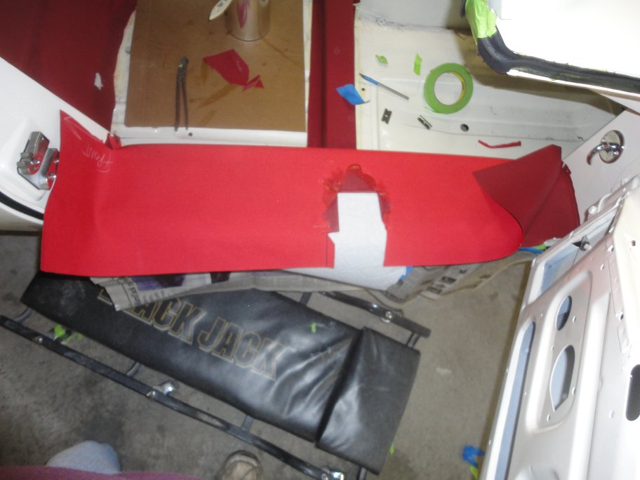 34) The sill vinyl is only glued along the perimeter to prevent wrinkles. The first step was to glue the vinyl at the top, extending beyond the sill so that the
ends can be wrapped around the lip when the chrome trim is applied. Then the vinyl was to be cut, glued and folded to fit the contour of the crossmember. In this picture
the notch for the crossmember is already dressed. This must be done with care as to not allow any of the foam or body color from showing once the sill vinyl is glued
down around the crossmember.
34) The sill vinyl is only glued along the perimeter to prevent wrinkles. The first step was to glue the vinyl at the top, extending beyond the sill so that the
ends can be wrapped around the lip when the chrome trim is applied. Then the vinyl was to be cut, glued and folded to fit the contour of the crossmember. In this picture
the notch for the crossmember is already dressed. This must be done with care as to not allow any of the foam or body color from showing once the sill vinyl is glued
down around the crossmember. |
 35) With the sill vinyl glued down to the floor, the top of the sills were detailed. This picture shows the original vinyl piece and how it was
folded to meet the A-pillar. The vinyl is folded under itself on the outbord edge and is glued up onto the vertical face to hide the gap
between the sill vinyl and the A-pillar hardura.
35) With the sill vinyl glued down to the floor, the top of the sills were detailed. This picture shows the original vinyl piece and how it was
folded to meet the A-pillar. The vinyl is folded under itself on the outbord edge and is glued up onto the vertical face to hide the gap
between the sill vinyl and the A-pillar hardura. |
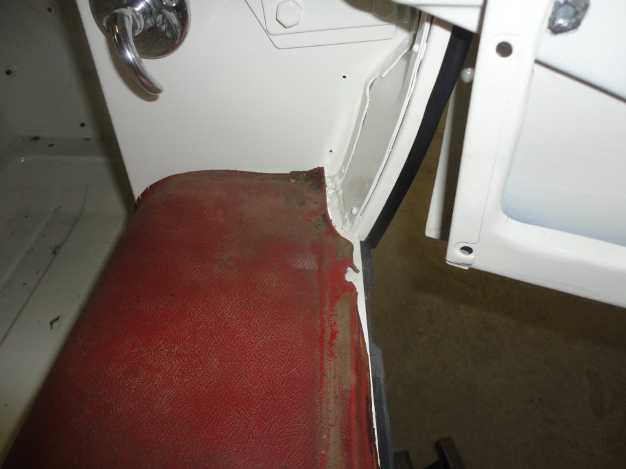
 36) This picture shows the original vinyl piece and how it was folded to meet the B-pillar. The vinyl is folded under itself and lies flat for about 3 inches and then
it is glued up onto the vertical face to hide the gap between the sill vinyl and the B-pillar trim panel.
36) This picture shows the original vinyl piece and how it was folded to meet the B-pillar. The vinyl is folded under itself and lies flat for about 3 inches and then
it is glued up onto the vertical face to hide the gap between the sill vinyl and the B-pillar trim panel. |
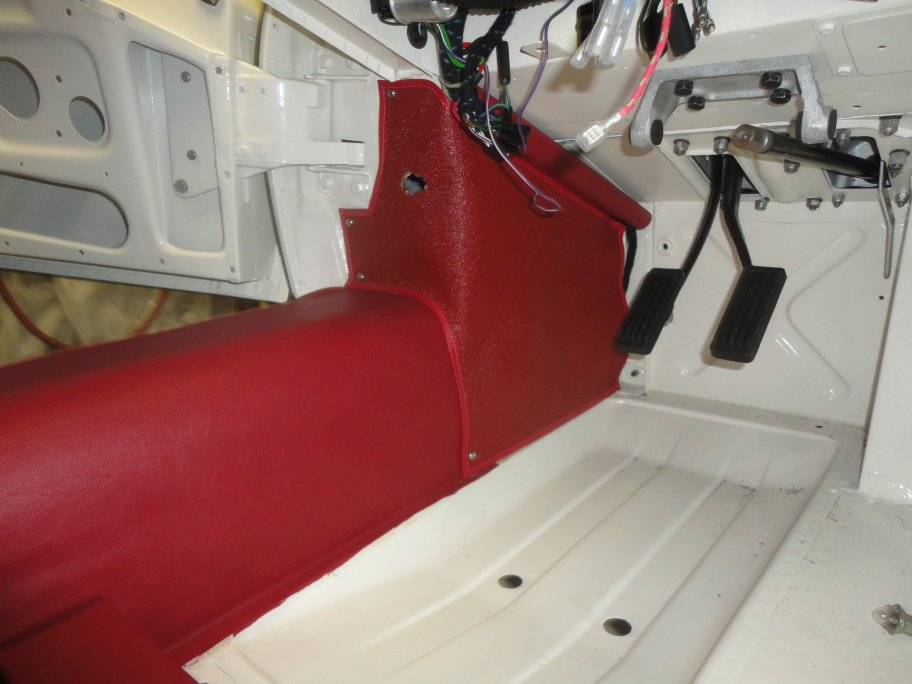
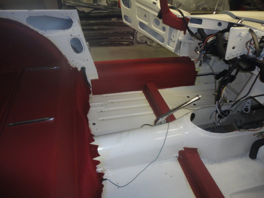 37) In this picture the sills and crossmembers have been covered. I chose not to install the chrome sill trim until much later in the project to prevent it from
being scratched.
37) In this picture the sills and crossmembers have been covered. I chose not to install the chrome sill trim until much later in the project to prevent it from
being scratched. |
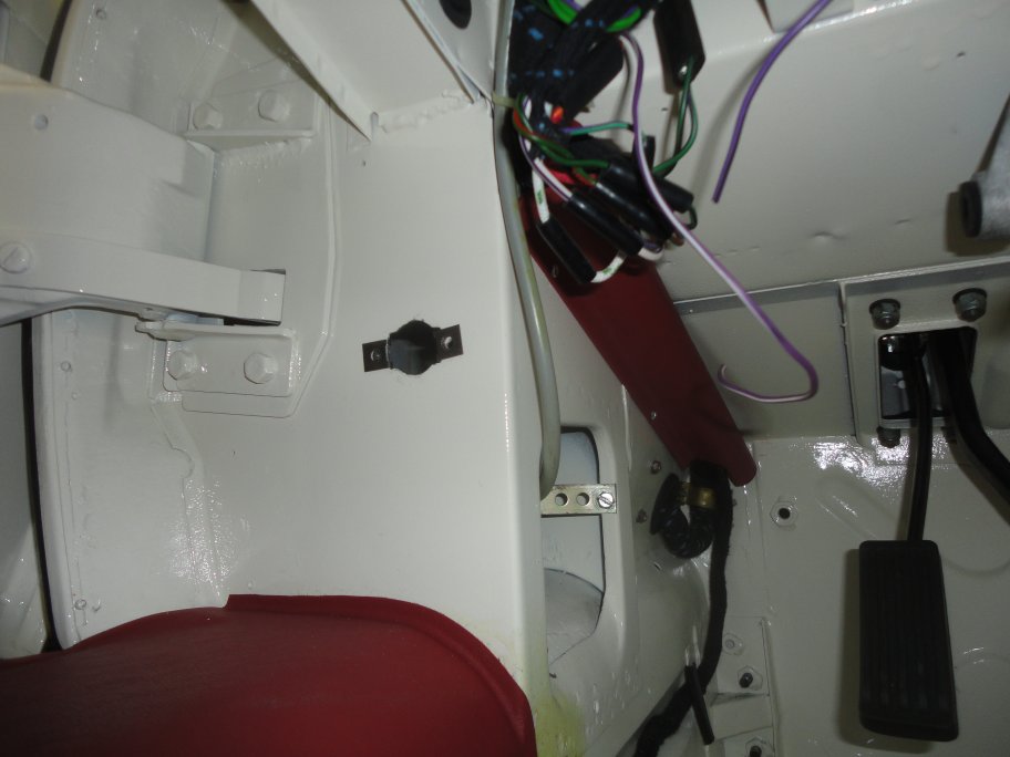 38) The A-pillars were next. The engine harness comes into the cabin through the left side bulkhead. The harness is covered with a vinyl wrapped cap that is held
in place with pop-rivets.
38) The A-pillars were next. The engine harness comes into the cabin through the left side bulkhead. The harness is covered with a vinyl wrapped cap that is held
in place with pop-rivets. |
 39) Originally the factory had glued a thick piece of felt paper to the forward part of the sills (side bulkheads) and then glued the A-pillar hardura to it.
The felt paper helped to hold the hardura flat, much like the felt paper on the cubby floor. In my case I opted to use a piece of foam.
39) Originally the factory had glued a thick piece of felt paper to the forward part of the sills (side bulkheads) and then glued the A-pillar hardura to it.
The felt paper helped to hold the hardura flat, much like the felt paper on the cubby floor. In my case I opted to use a piece of foam. |
 40) The hardura trim is glued in place except for the face of the A-pillars, which are screwed down.
 |