 1) Rebuilding the IRS (Independant Rear Suspension) is expensive and requires special tools. If you are not comfortable using a press and
a dial indicator, you are better off having someone else do the job. What I am documenting here is the process that I went through. I am not
responsible for any swearing, blood loss or any other issues relating to the assembly of your IRS.
1) Rebuilding the IRS (Independant Rear Suspension) is expensive and requires special tools. If you are not comfortable using a press and
a dial indicator, you are better off having someone else do the job. What I am documenting here is the process that I went through. I am not
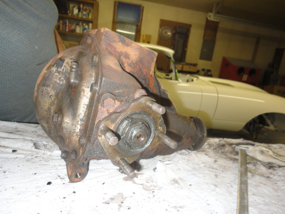
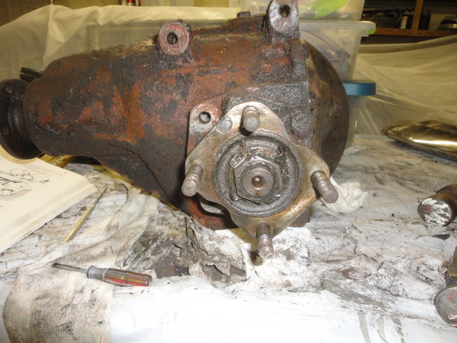
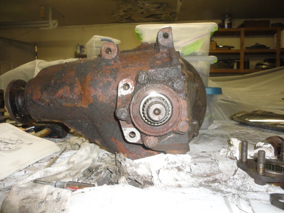
responsible for any swearing, blood loss or any other issues relating to the assembly of your IRS. The process starts with the differential removed from the cage and the brake system removed.A little degreasing is recommended. |
 2) I started with the propeller shaft (input) flange. This what the drive shaft bolts to.
 |
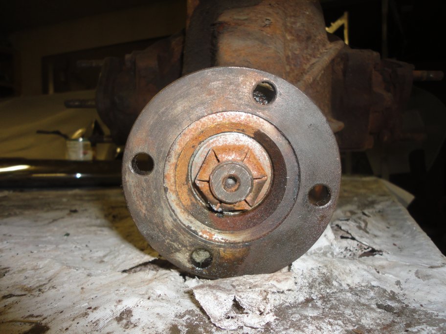
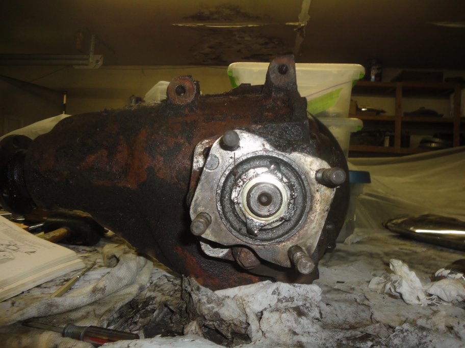
 3) I used an impact wrench to take the locking nut off. A breaker bar can be used, but you have to put a brace inbetween the bolts of one of the outshafts
to prevent the input shaft from rotating.
3) I used an impact wrench to take the locking nut off. A breaker bar can be used, but you have to put a brace inbetween the bolts of one of the outshafts
to prevent the input shaft from rotating.
|
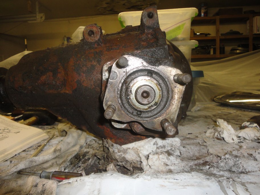
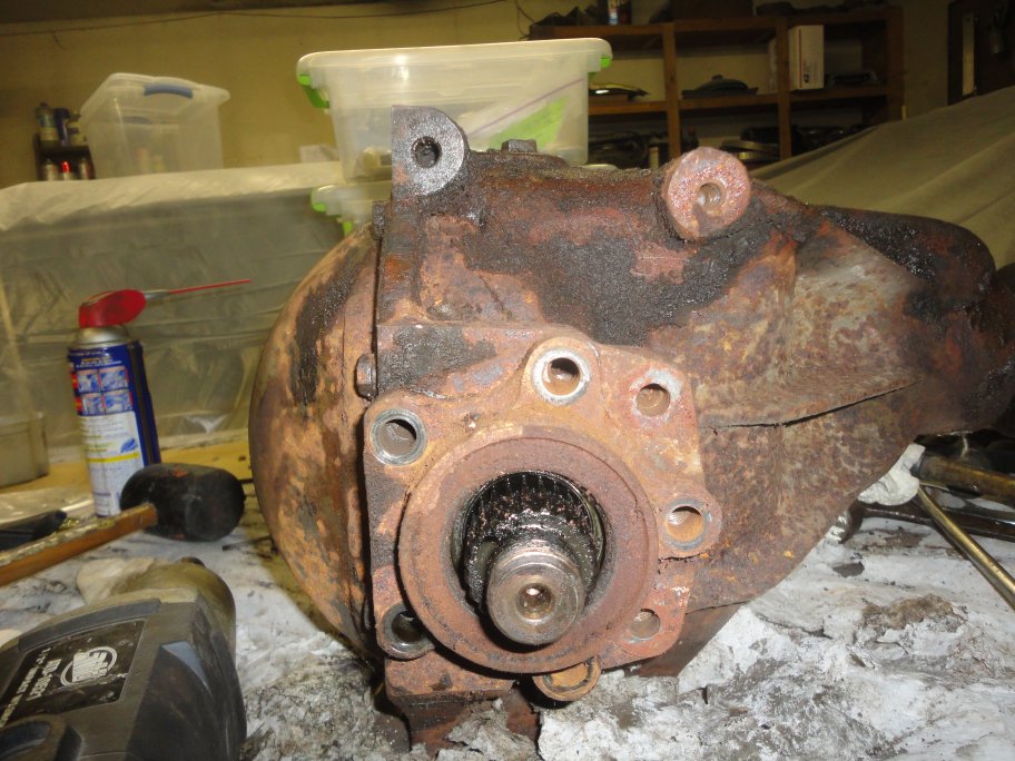
 4) The flange must be removed using a puller.
 |
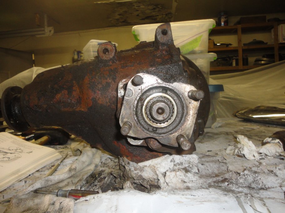
 5) The output shafts are removed next. You can take them out as whole assemblies, but it is a lot easier to dismantle them while still attached to the diff housing.
The first thing to do is bend the ears back from the locking plate and the nut can be removed with an impact wrench.
5) The output shafts are removed next. You can take them out as whole assemblies, but it is a lot easier to dismantle them while still attached to the diff housing.
The first thing to do is bend the ears back from the locking plate and the nut can be removed with an impact wrench.
|
 6) Once the nut is removed the locking plate will slip right off. In this picture you can see that the locking plate is keyed into the output flange to
keep it from spinning.
6) Once the nut is removed the locking plate will slip right off. In this picture you can see that the locking plate is keyed into the output flange to
keep it from spinning. |
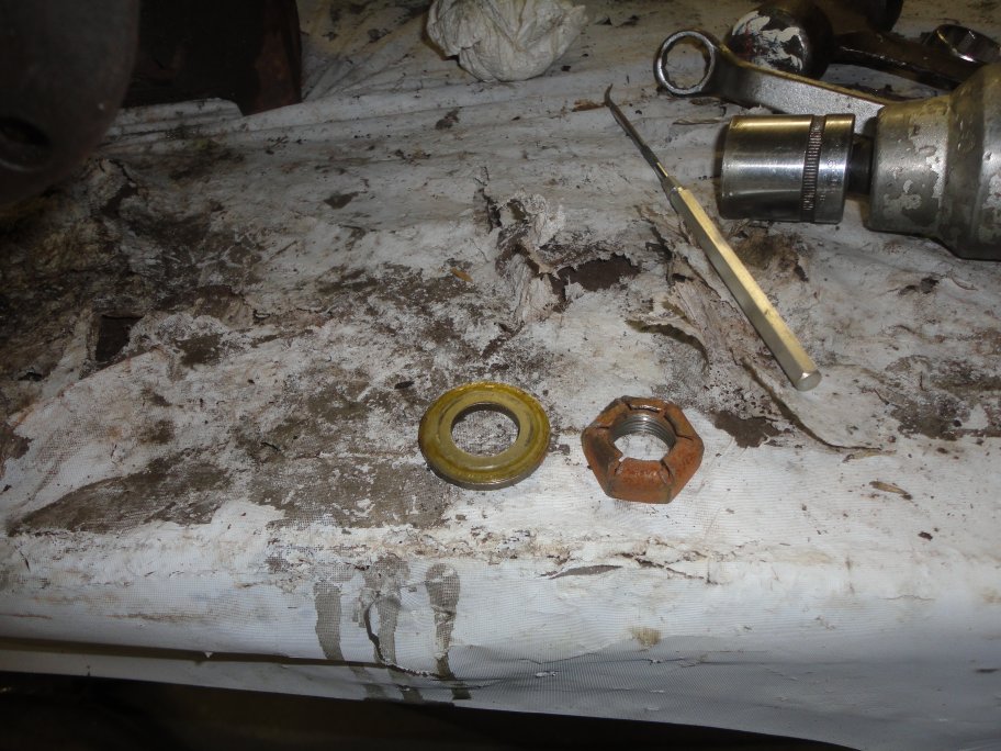
 7) Behind the locking plate is a washer.Without it, the locking plate would deform when the nut is tighten down.
|
 8) The output flange is splined and can be easily extracted by hand.
|
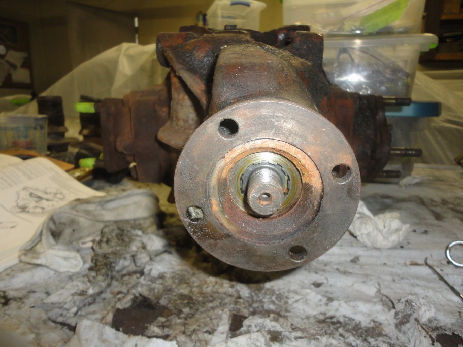
 9) With the output flange removed the output shaft seal is visible. You still would need to remove the output flange housing if
you needed to just change the seal.
9) With the output flange removed the output shaft seal is visible. You still would need to remove the output flange housing if
you needed to just change the seal.
|
 10) The output flange housing is held on by 5 bolts.
|
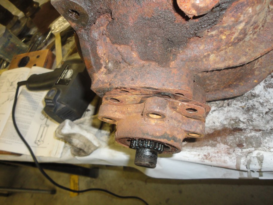 11) The easiest way to remove the housing is to rotate it by tapping on it with a hammer and a block of wood. And then tap on one of the ears
from behind to pop it out. You don't want to get behind it with a screwdriver and risk damaging the machined faces, which will cause the housing not
to seat properly when reassembled.
11) The easiest way to remove the housing is to rotate it by tapping on it with a hammer and a block of wood. And then tap on one of the ears
from behind to pop it out. You don't want to get behind it with a screwdriver and risk damaging the machined faces, which will cause the housing not
to seat properly when reassembled.In this picture you can see the special shims that are used to set the clearance between the inner output shaft bearing and the outer differtial bearings. It's best to keep with shims together and mark which side they came from. |
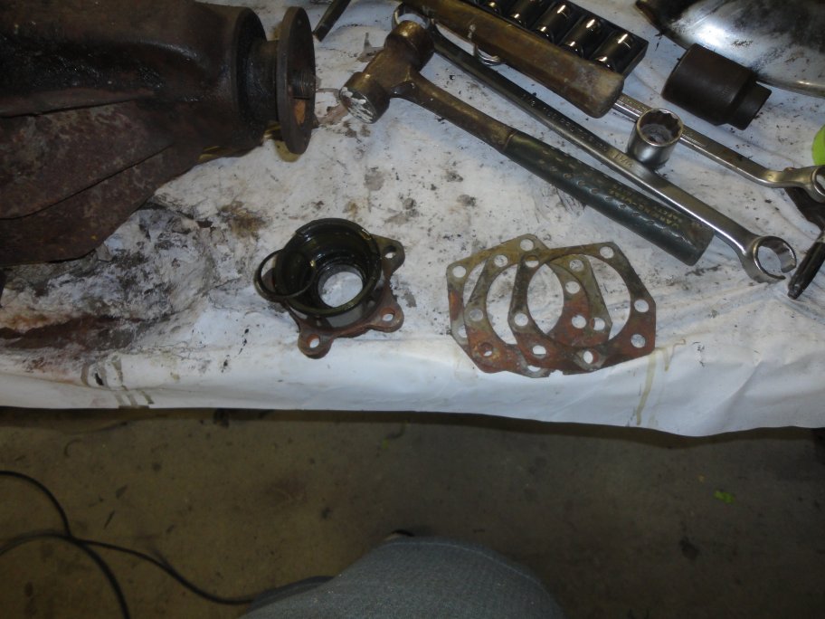 12) Here the output shaft housing and shims are removed from the diff housing. The shims on earlier cars like this one are a little bigger and have 2 extra holes
for shimming of the brake calipers. I was unable to find these shims reproduced. They only seem to reproduce a 5 hole version, which is fine, but you have to
use more shims on the calipers. more on this later.
12) Here the output shaft housing and shims are removed from the diff housing. The shims on earlier cars like this one are a little bigger and have 2 extra holes
for shimming of the brake calipers. I was unable to find these shims reproduced. They only seem to reproduce a 5 hole version, which is fine, but you have to
use more shims on the calipers. more on this later.
|