 15) The next part of the assembly is to install and set the float for the outer fulcrum bearings.
|
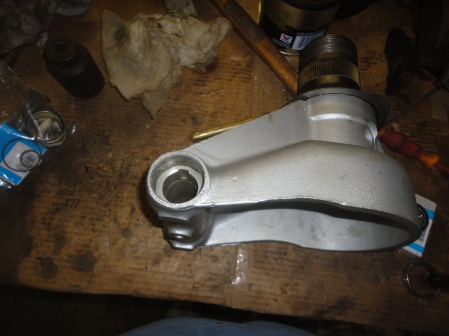
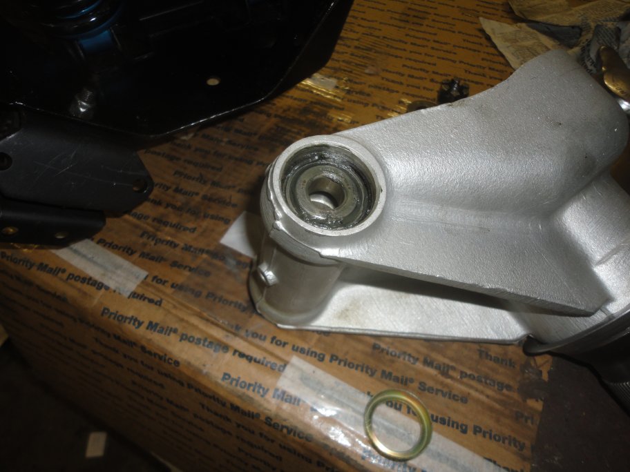
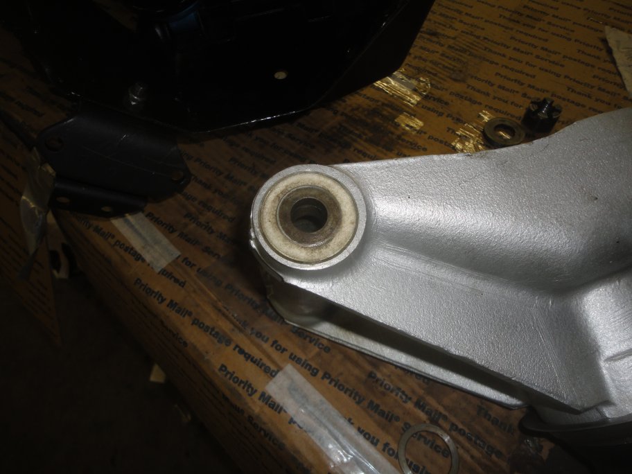
 16) The process begins with the installation of the outer bearing races on each side of the hub housing. A large socket makes a great tool for driving in the outer races.
|
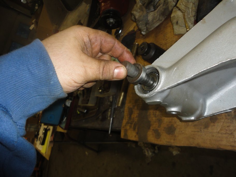
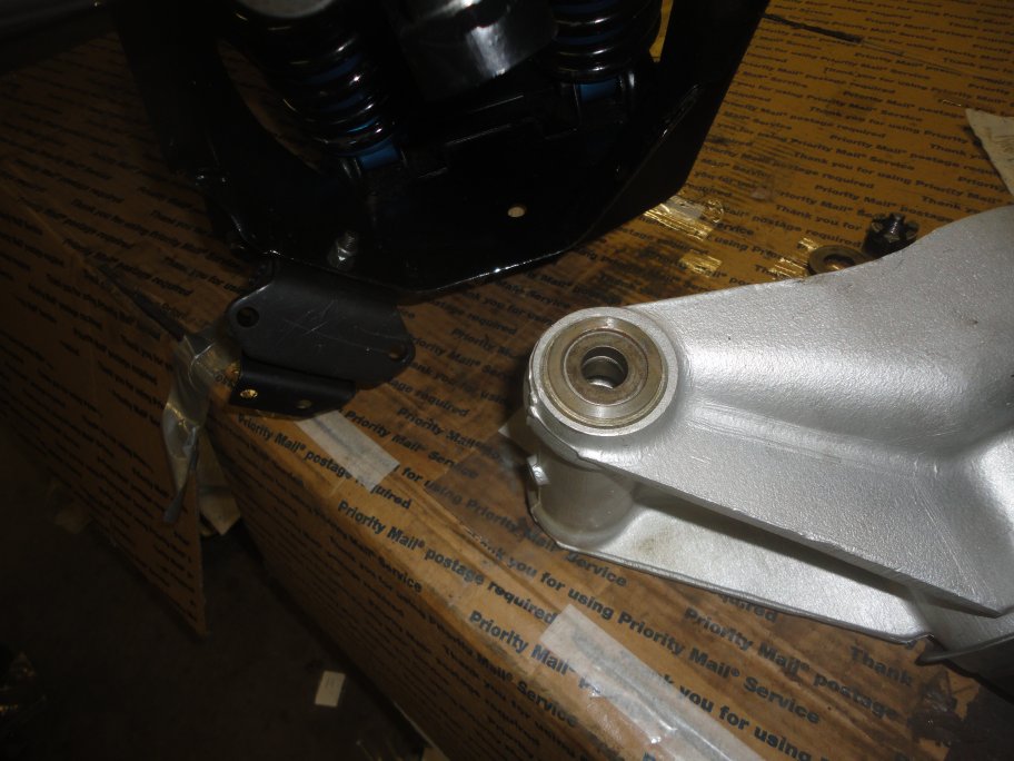
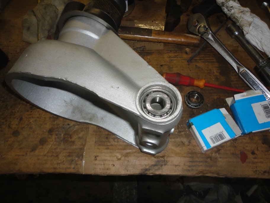 17) The inner portion of one bearing is set in place dry for the bearing float adjustment.
|
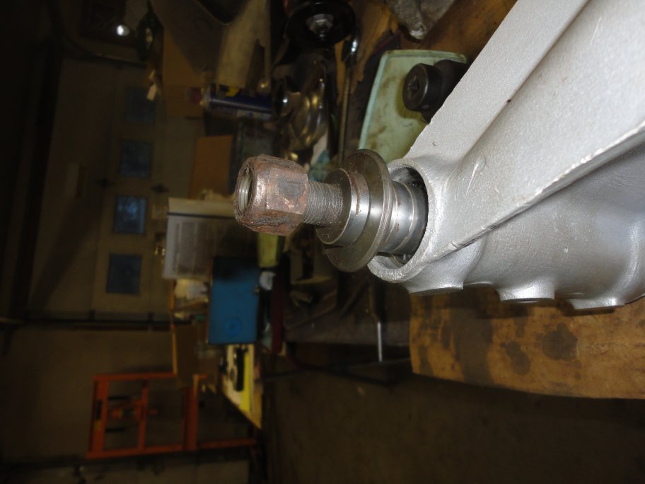
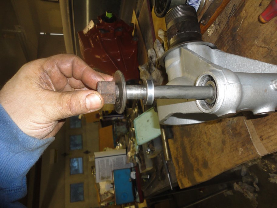 18) The fulcrum shaft, spacer, washer and nut are temporarily installed on one side to set the float. You may want to mount the hub assembly in a vise at this time (mounted by the nut).
|
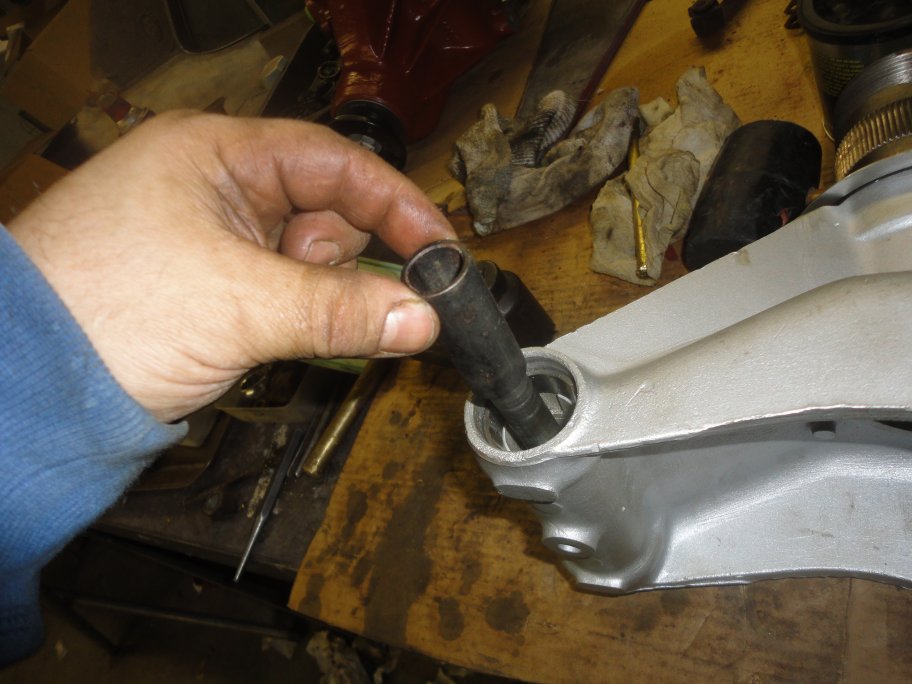 19) Two short tubes are installed on the fulcrum shaft, which are seperated by shims in the middle. You must alter the number and thicknes of the shims to set the float. Here the first spacer tube is installed.
|
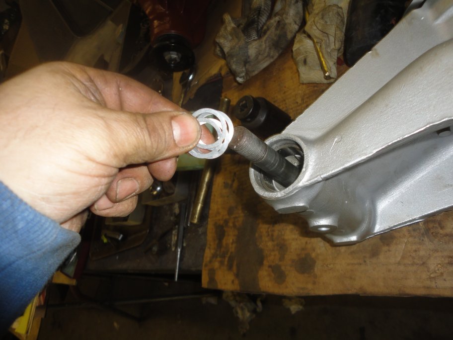 20) Next goes the shims. If you are installing new bearings, you should install more shims then necessary to get a large enough float to measure. Usually 0.010" - 0.020".
|
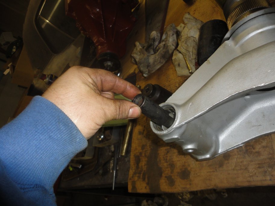 21) Next goes the second spacer tube.
|
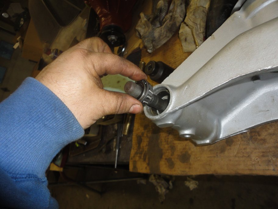 22) And then the inner portion of the second bearing.
|
|
|
|
 23) This spacer normally has a felt seal around it, but for now it is only needed as a spacer for setting the float. The rebuild kits from SNG Barratt come with new seals and spacers (but not the spacer tubes), so using the old spacers is a good idea to prevent the new ones from getting dirty and or damaged.
|
 24) A stack of old spacers and the original nylock nut are installed. The nut is tightened down all the way. Unfortunately I did not take any pictures of the float measurement, so you will have to use your imagination. The float is measured by first mounting the hub assembly in a vise by a fulcrum shaft nut. A dial indicator is mounted on the opposite (free) end of the hub assembly and is set to contact the surface of the fulcrum shaft . Using a pry large screwdriver or small prybar, you pry between the vise and the hub assembly and measure the deflection of the dial indicator. Ideally it should read 0.005" +/-.002". If it doesn't then you will have to add or remove shims to get the proper float. Once set you take the fulcrum shaft
| zxs
 25) With the flaot set, the fulcrum shaft can come out and the bearings can be greased. It is recommended in the service manual to create a dummy shaft (less than the width of the hub assembly) to hold the tube spacers and shims in place until the hub assembly is installed. You could make one from a wooden dowel rod from your local hardware store. I just used a tapered punch to line things up during the assembly.
|
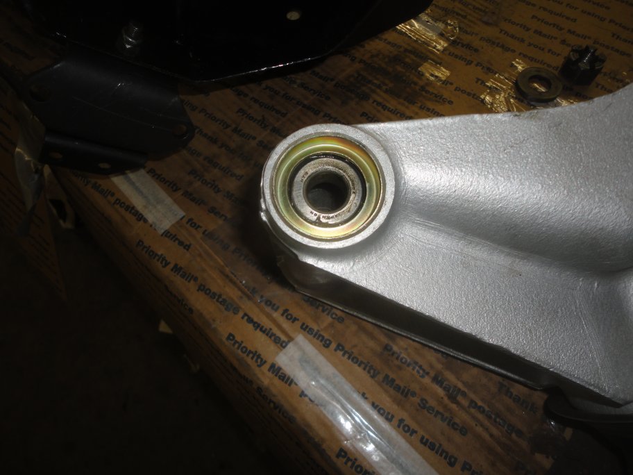 26) The assembly contiues with the installation of the felt seal cup. It can be installed with a rubber mallet or a block a wood and a hammer.
|
 27) The felt seal goes in next.
|
 28) Followed by the spacer.
|
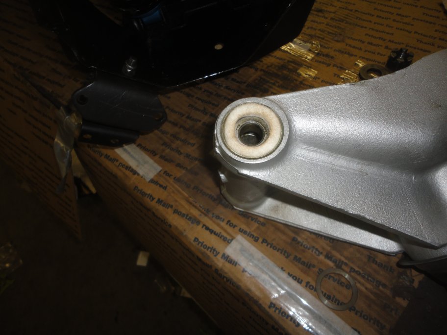
 29) The last piece to go in is this washer that applies pressure to the felt seal when the hub assembly is installed. It is a good idea to tape these in place until you are ready to install the hub assemblies on the lower arm.
|
|