|
|
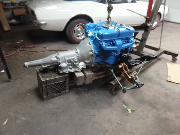
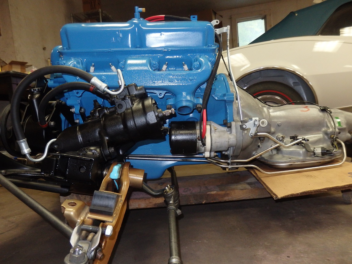
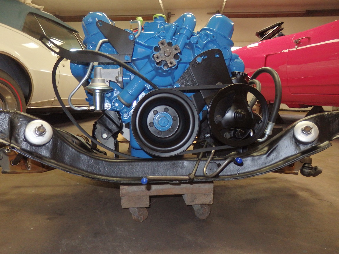
Here's the engine mounted on the K-Frame, but not quite ready to install. It's a lot easier to install a lot of items on it before it goes in, then crawl all over and under the car trying to install things. |

|
|
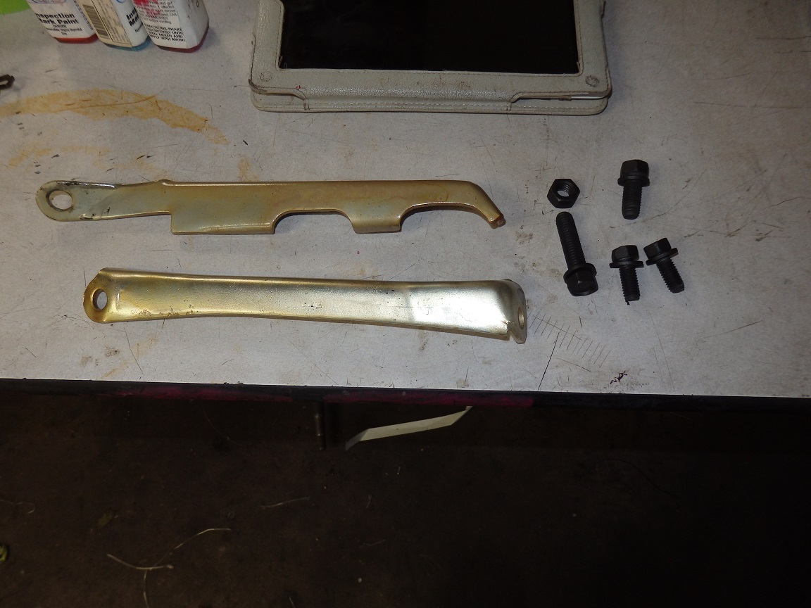
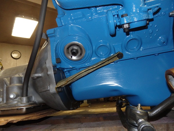
318's have these braces between the block and transmission. I replated the orginals and installed them using new hardware from AMK Products. |
|
| Here the new Carter fuel pump and fuel lines were installed. The new Carter fuel pump is a close representation of the original one. |
|
|
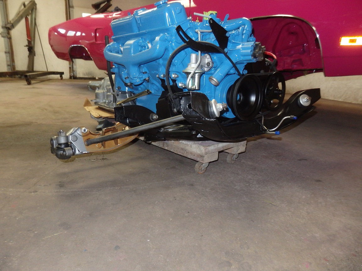
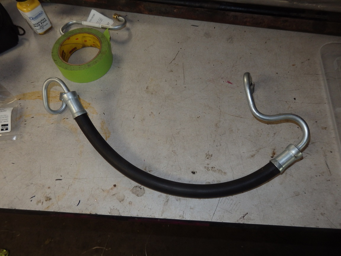
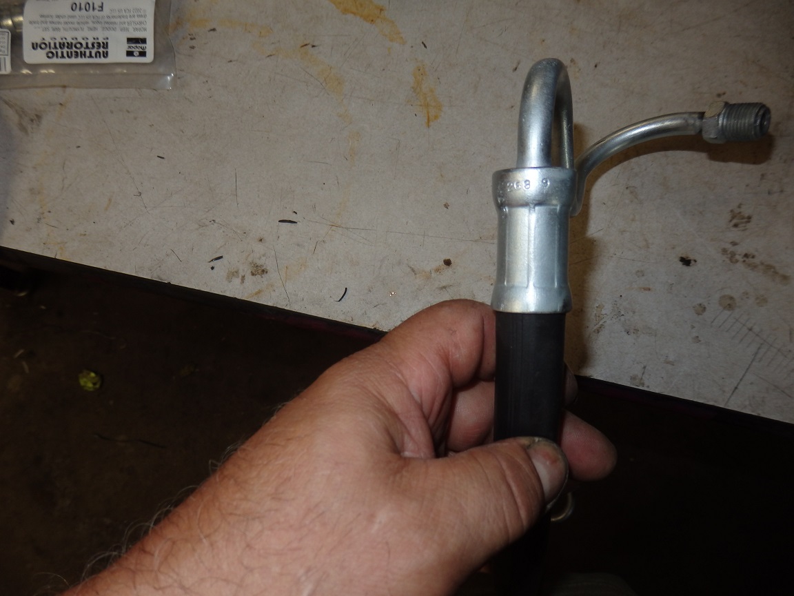
Next up was the Power Steering Pump and Starter. I restored both of them myself instead of sending them out. I also replated the original power steering hose. You can see the part number and date code in the picture on the right. |

|
|
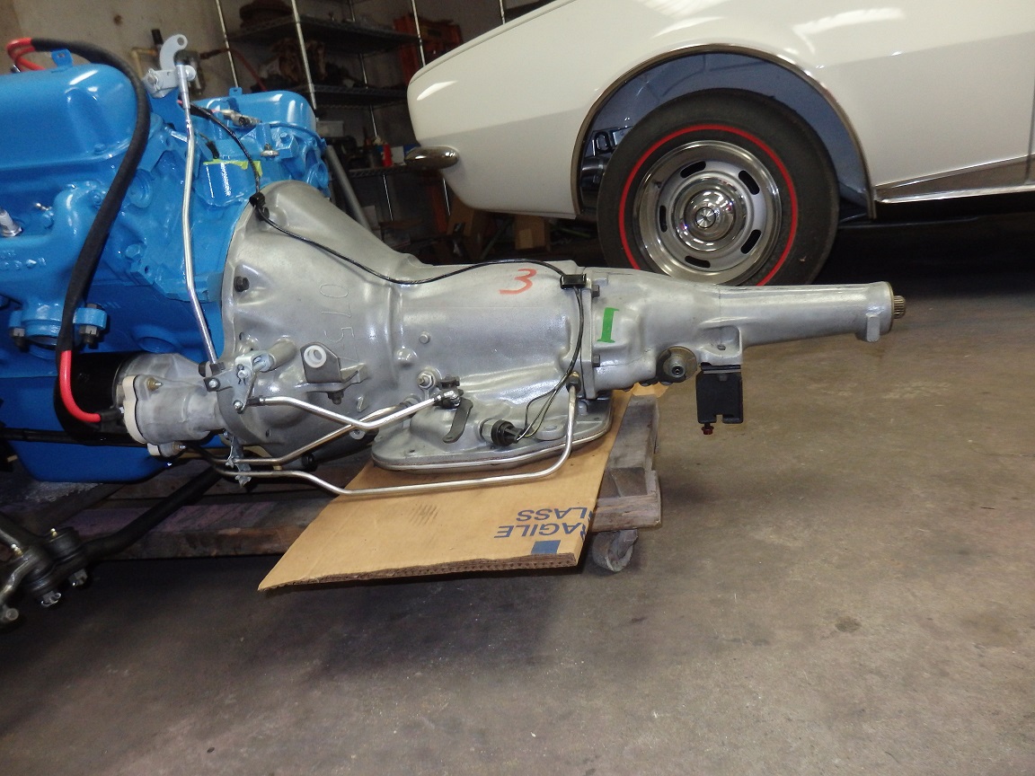
Next up was the transmission lines, wiring and kickdown linkage. One thing to note was the bracket at the starter for the transmission lines. This is an original part that I replaced. This is a very comon part to be missing as it
is removed when replacing the starter. |

|
|
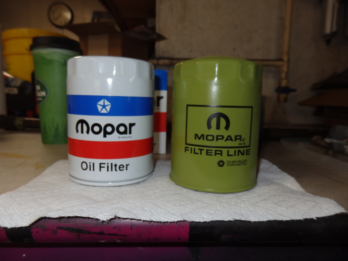
Here are a couple repo oil filters. The green one is more like the one that was on it from the factory. It even has a raised "M" on the top. The white one is more like the service replacements from 1972 and up. |
|
|
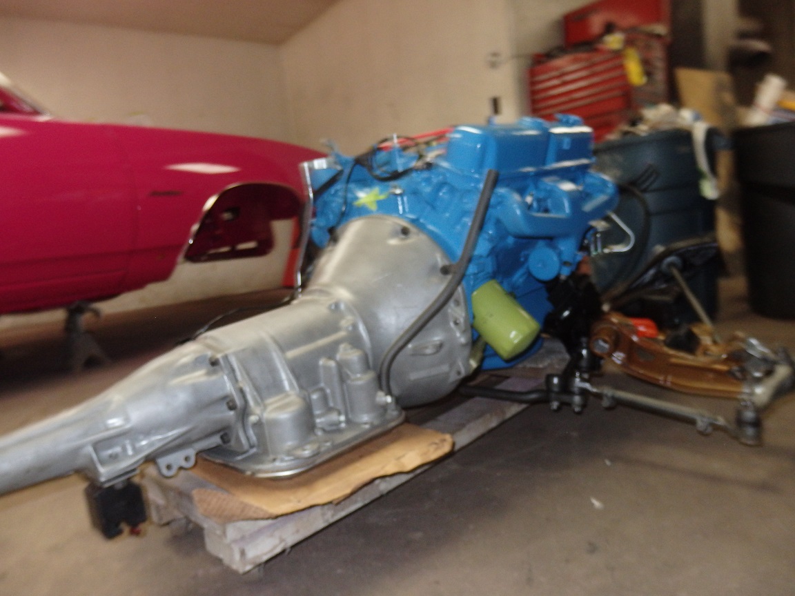
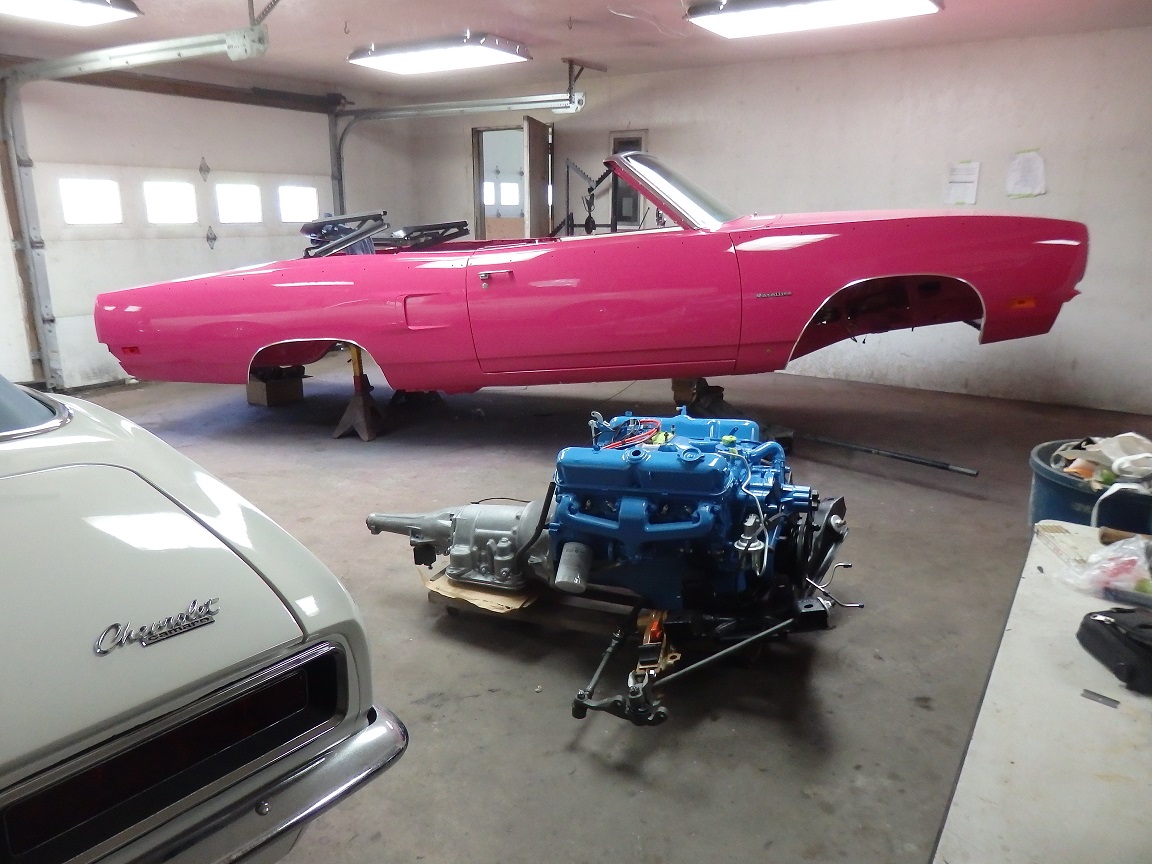
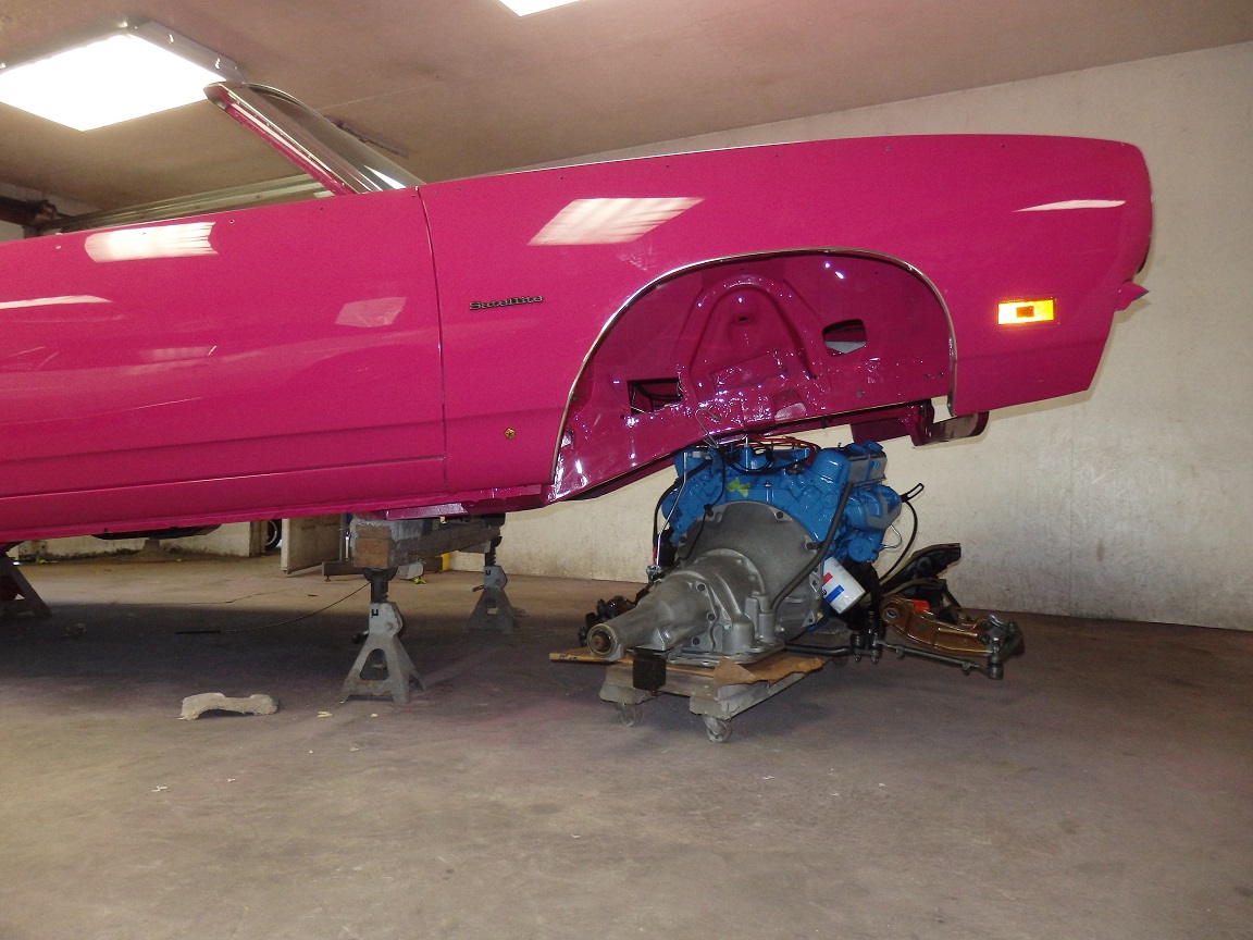
Now for the installation. As with my Challenger I raised the front as high as I could get it so that the engine would fit into the wheel well and under the frame rail. It helps to have no carberator, distributor or alternator installed for
clearance reasons. |


|
|
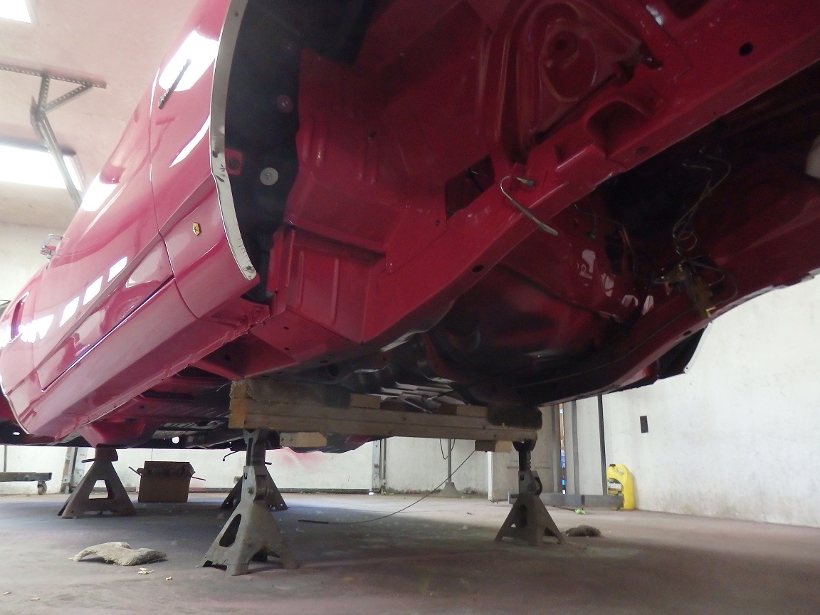
In the first picture you can see that I turned the engine 90 degrees and pushed it under the car. In the second picture I spun it around to the correct orientation. Using a couple jacks I lowered the body and then raised the
engine up in place. Then bolted her up. The whole process took be about an hour, alone.... I don't think that engine bay has looked that good since the car was built. It wasn't long after it was sold the pink got covered with Ziebart undercoating treatment. |
|
|
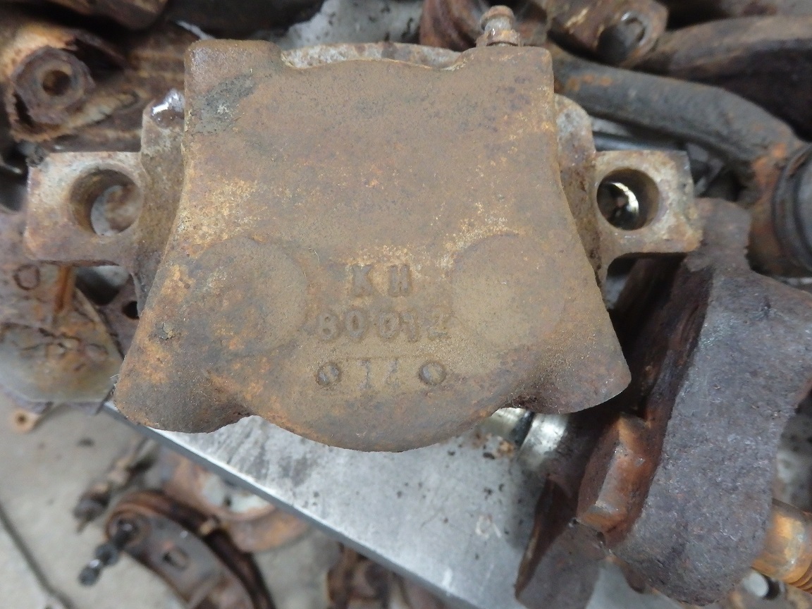
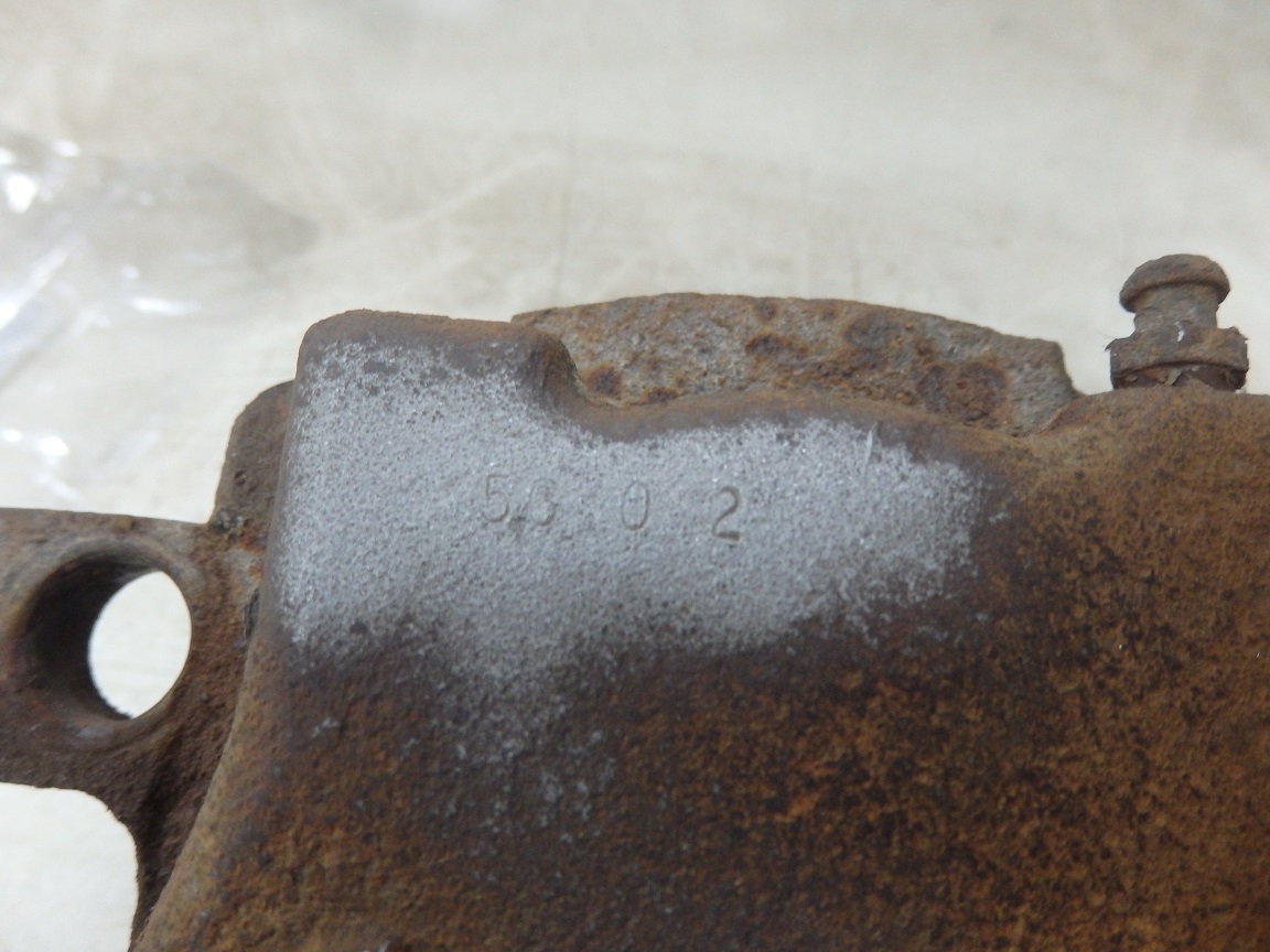
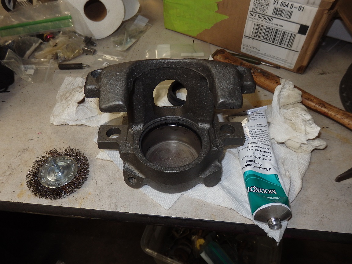
Here is one of the original calipers that came off the car. They are Kelsey Hayes PN 80012, which are well sought after since they are a 1970 only wide-mouth design. The cast date of 14 means that they were cast on the 14th day of 1970, which is January 14th. Sandblasting revealed the assembly date code of 56 0 2, which translates to the 56th day of 1970 (February 25th, 1970), 2nd shift. |

|
|
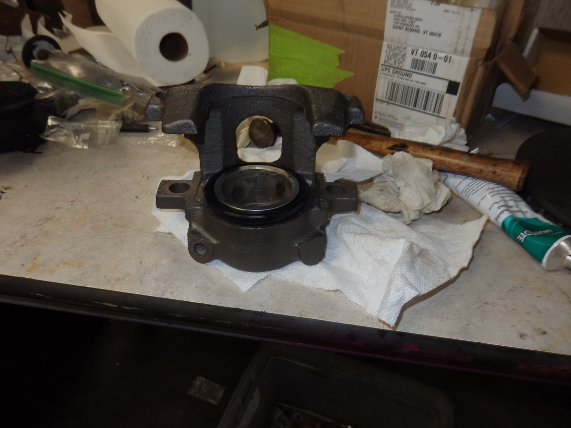
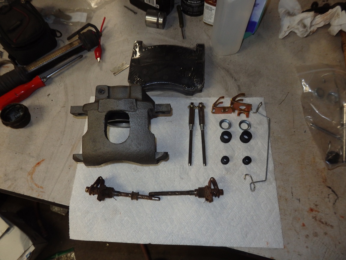
It took quite a lot of effort to pull the pistons out of the calipers. The rest was a breeze. I sandblasted the housings and honed out the bores. I painted the housings with a high temp castblast paint by Seymour and
baked the paint. Repo pistons, seals and boots are readily available. I actually bought mine from a member of www.forbbodiesonly.com who has been selling off quite a few 1970 RoadRunner parts. There are a few videos online that show how to rebuild the calipers. Probably the biggest help from one of the videos was explaining that Molykote Electrical Insulation Compound #4 is the best lubricant for rebuilding calipers. |


|
|
As with the calipers the spindles and caliper brackets were sandblasted, painted with seymour high heat castblast and baked. Again my source at www.forbbodiesonly.com came through and sold me a really nice pair of disc brake dust shields. I sandblasted, epoxy primed and painted them black. You can always tell the repos from the originals as the originals have crisper details and they have "L" & "R" stamped in them (not visible in these pictures). |

|
|
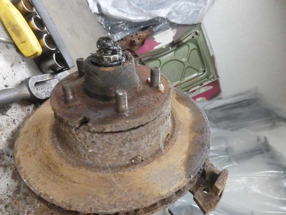
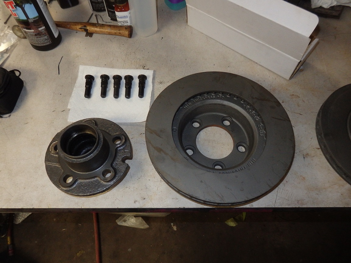
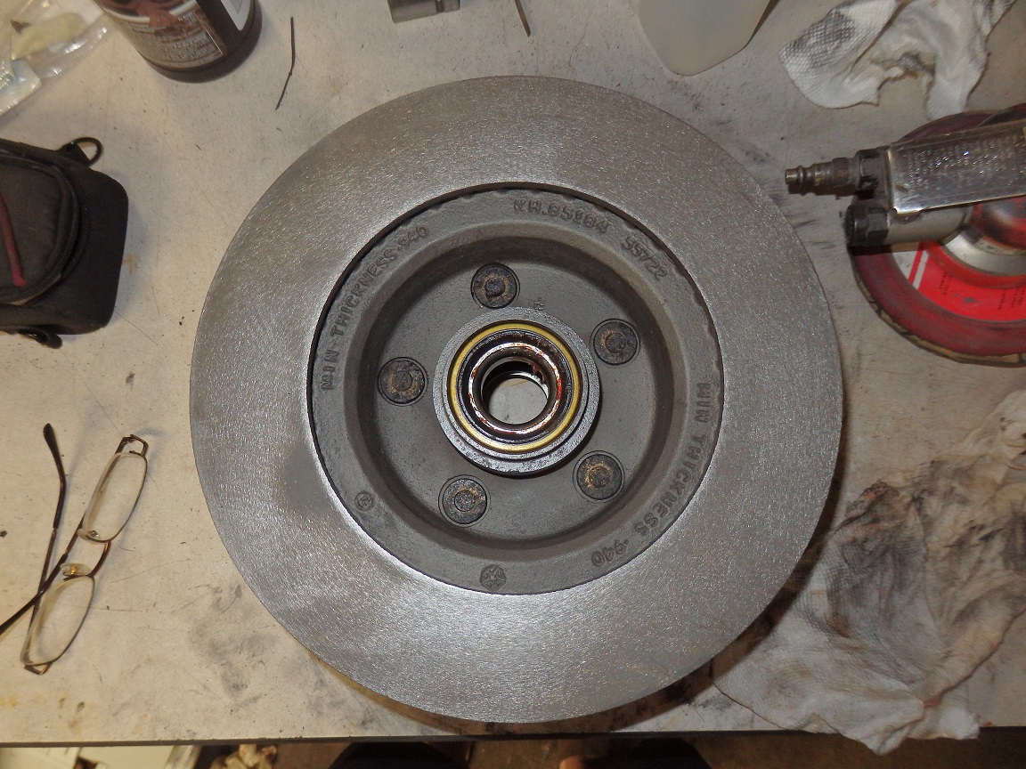
Older Mopars like this one use 2-piece rotors. They aren't reproduced, so you can either buy new 1-piece replacements or find good used ones if yours can't be turned. My originals were junk, but I was able to get a used pair, without the hubs,
that had one good turn left on them. To take them a part you just press the studs out and the hub comes right off. crappy design really.... I kept my original hubs and turned the replacement rotors. After sandblasting and painting with castblast, I put them back together. It should be noted that up to and including 1970 Chrysler put reverse thread studs on the right side of the car. So you have to pay attention when taking off your wheels and putting the rotors on the correct side. The reverse threaded studs have an "R" stamped on their face and are copper plated. |

|
|
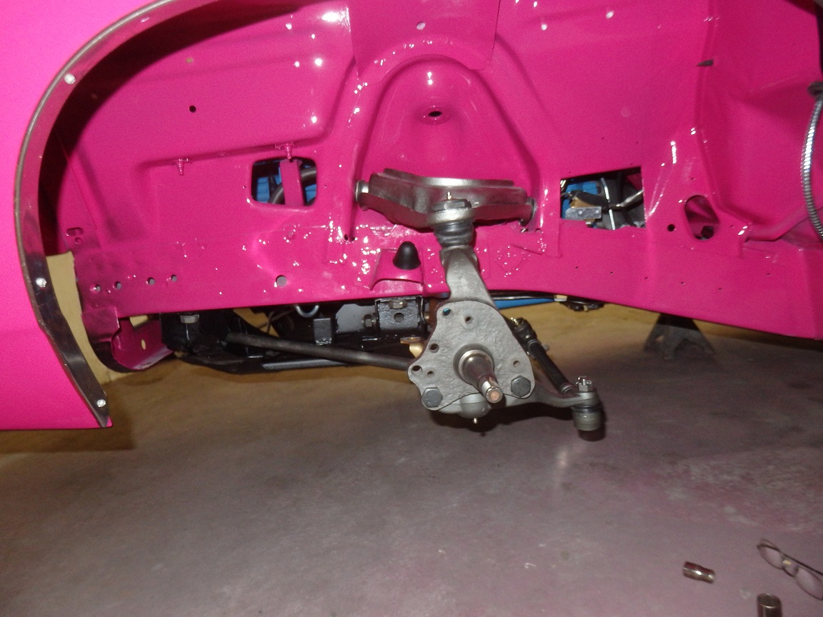
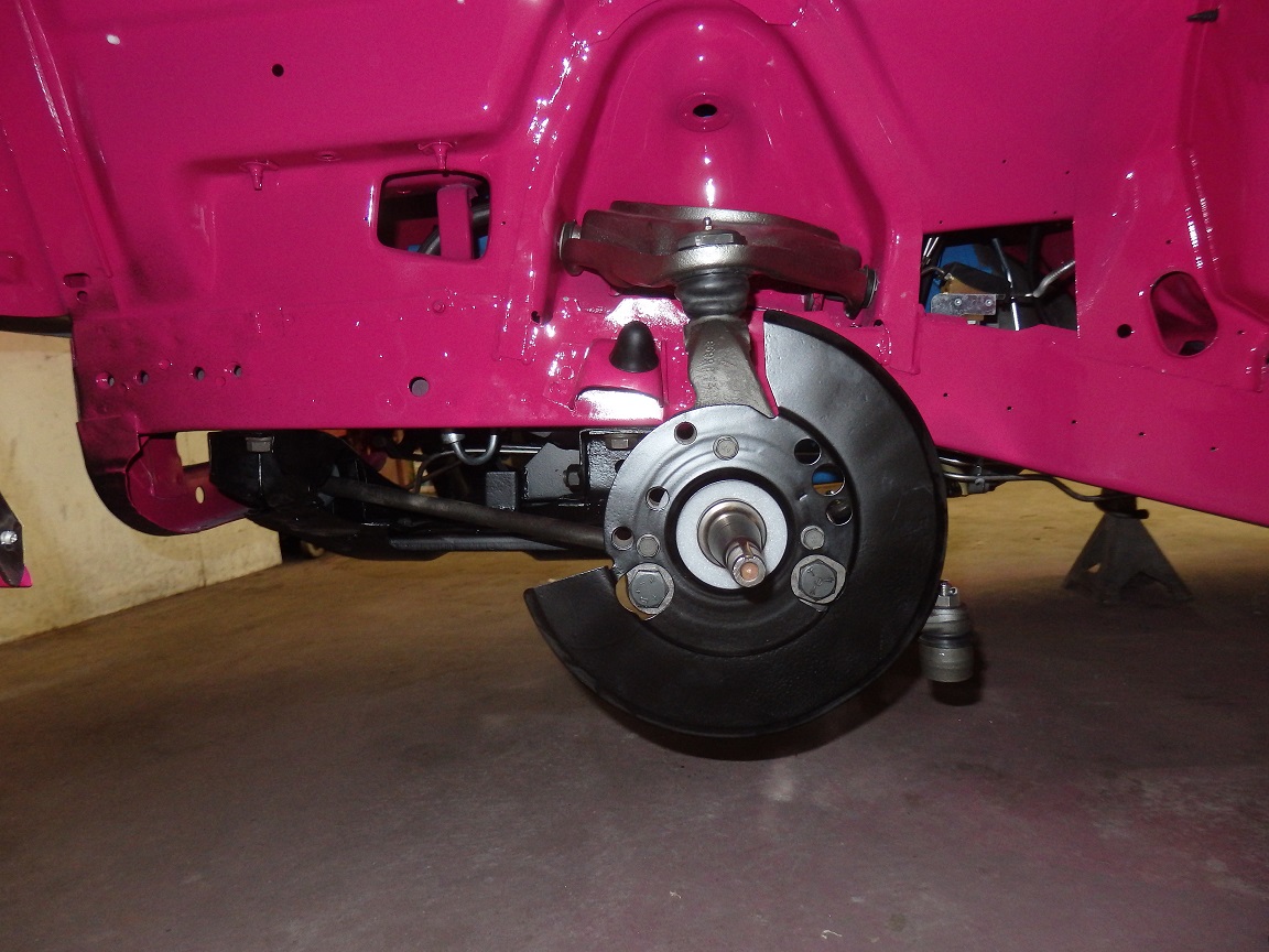
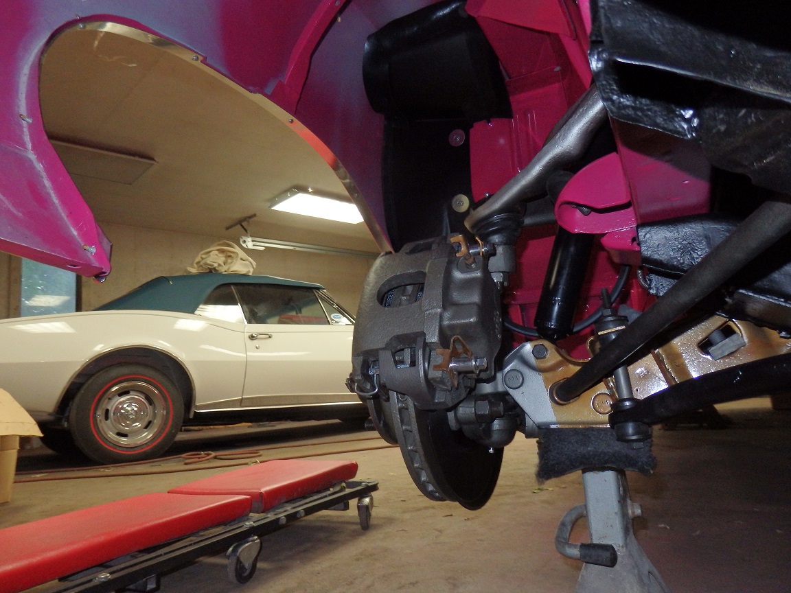
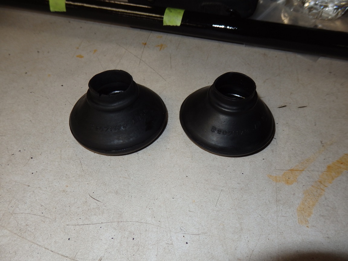
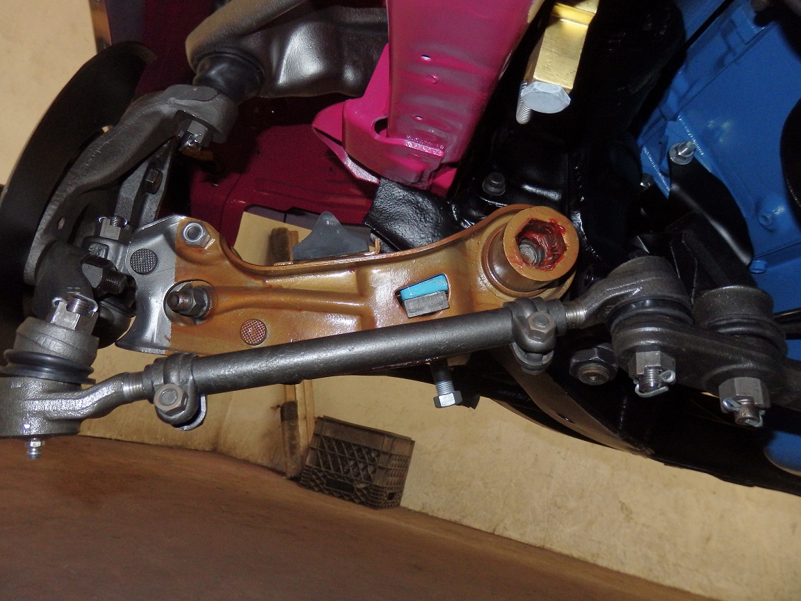
With all the piece parts done, it was time to put the front suspension and brakes together. Sorry I didn't take any pictures of rebuilding the upper control arms. The originals were far to rusty to reuse. I was able to buy a nice used set for $100. I sandblasted them, pulled the balljoints and bushings. Then I primed them with epoxy primer and painted them with Seymour stainless steel paint to give them a natural bare steel look. The lower balljoints are Moogs. They just bolt right on to the spindle. Before the dust shield goes on, there is a white foam gasket, which keeps dirt out. |


|
|
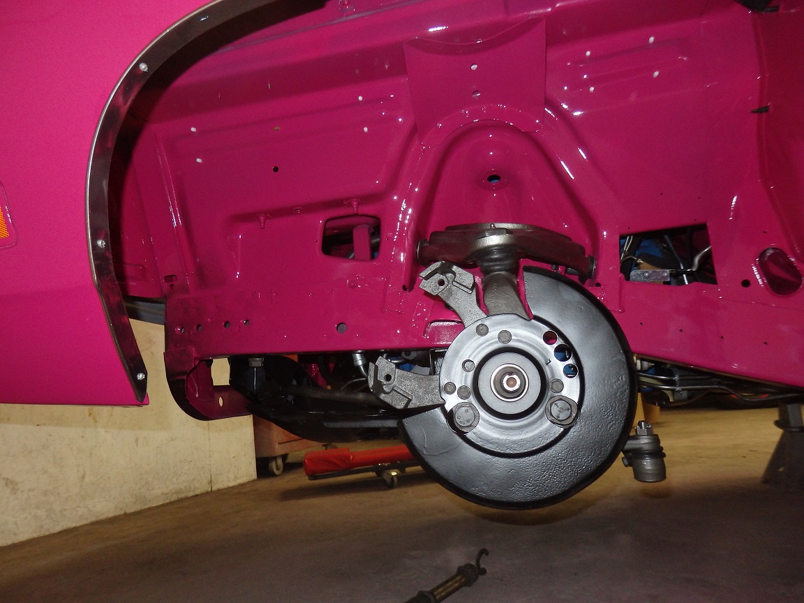
Then the rotors and calipers go one. You can see in the last couple pictures the wide opening, wide mouth, on the calipers. This is the quick way to tell you have the 1970 version. |

|
|
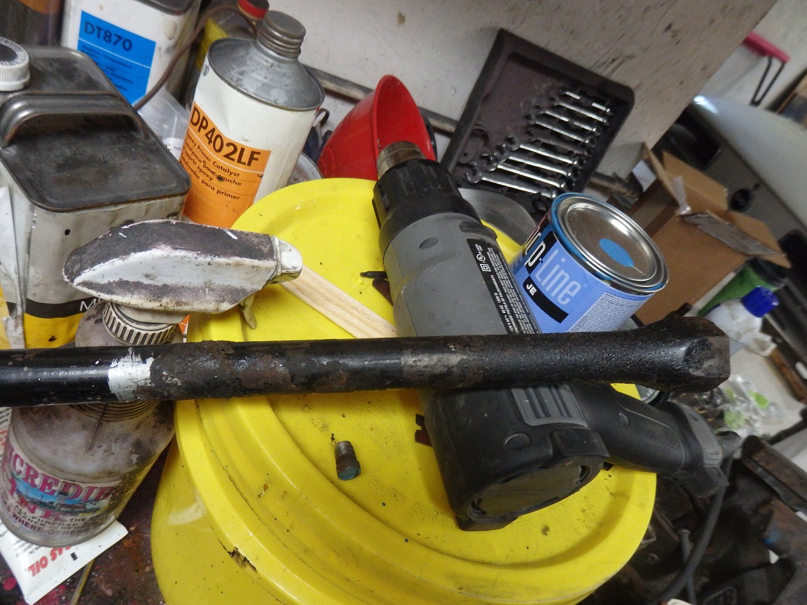
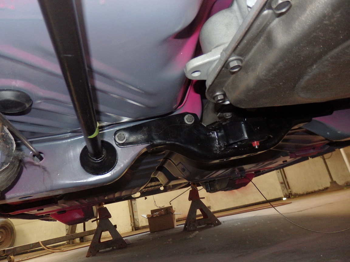
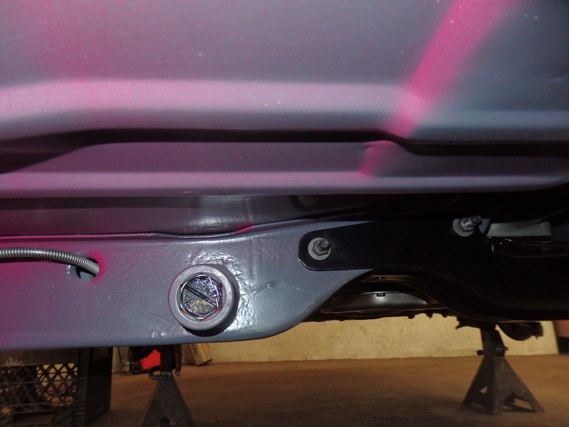
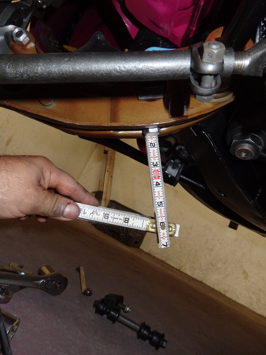
Next to go on was the torsion bars, but first they needed to be stripped and painted. Left and right torsion bars are different and they have part numbers stamped on them. There are different versions of them
so the factory put colored markings on them for quick identification. This car had silver markings. 2 designated the left side and 1 designated the right side. I measured the location of the markings, but I did not
bother putting them back on until after the bars were installed. |
|
Now for the actual installation. Starting from the leftmost picture:
|