 27) Before moving on to the wiring a few firewall items need to be installed. The blanking plate that goes behind the windshield washer
jar bracket is installed with 4 pop-rivets.
27) Before moving on to the wiring a few firewall items need to be installed. The blanking plate that goes behind the windshield washer
jar bracket is installed with 4 pop-rivets.
|
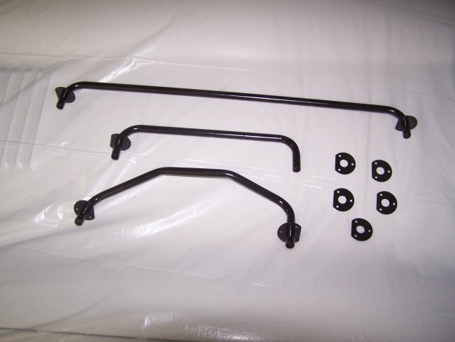
 28) The heater pipes are installed inside the cowl and are quite tricky to install. The first one to be installed is the long bottom
one. From inside the car the bottom center side goes in first, but will not go into position correctly. The left side must be
inserted inside the cowl, raised as high gas possible and be pulled up and to the left as much as possible. This allows the opposite
side to drop down below an inner cowl reenforcement. Then both ends may be pushed out the holes in the firewall. If the heater pipes are new, they
not want to pull through. So some force or pre-filing may be required.
28) The heater pipes are installed inside the cowl and are quite tricky to install. The first one to be installed is the long bottom
one. From inside the car the bottom center side goes in first, but will not go into position correctly. The left side must be
inserted inside the cowl, raised as high gas possible and be pulled up and to the left as much as possible. This allows the opposite
side to drop down below an inner cowl reenforcement. Then both ends may be pushed out the holes in the firewall. If the heater pipes are new, they
not want to pull through. So some force or pre-filing may be required.
|
 29) Collars are slipped over the end of the pipes and are pop-riveted in place. Standard pop-rivet guns will not reach, so the simplest solution
is to create a stack of small nuts and use them as a spacer, as shown here. The remainding heater pipes go in a lot easier.
29) Collars are slipped over the end of the pipes and are pop-riveted in place. Standard pop-rivet guns will not reach, so the simplest solution
is to create a stack of small nuts and use them as a spacer, as shown here. The remainding heater pipes go in a lot easier.
|
 30) The washer jets install rather easily. The question is, do they both point outboard, do the both point inboard, do they both point to the
left or to the right? Which way the squirters point seems too depend the the jets themselves. The squirters just thread
into the base. They are then adjusted/turned up or down depending on where you want the fluid to hit the windshield. In this case both jets
had to be pointed to the left of the car so that the squirters would not be too loose to stay in place.
30) The washer jets install rather easily. The question is, do they both point outboard, do the both point inboard, do they both point to the
left or to the right? Which way the squirters point seems too depend the the jets themselves. The squirters just thread
into the base. They are then adjusted/turned up or down depending on where you want the fluid to hit the windshield. In this case both jets
had to be pointed to the left of the car so that the squirters would not be too loose to stay in place.
|
 31) The fluid lines meet at a "T" fitting inside the cowl and are held in place with a PVC sleeved metal tab.
|
 32) The windshield wiper transmission is installed in pieces with the outer wiper posts installed first. The wiper transmission has an adjustment
cable that is used to set where the wipers stop whne they are turned off. The cable should be attached to the center wiper post
when it gets installed, or it will be very difficult to install the cable afterwords.
32) The windshield wiper transmission is installed in pieces with the outer wiper posts installed first. The wiper transmission has an adjustment
cable that is used to set where the wipers stop whne they are turned off. The cable should be attached to the center wiper post
when it gets installed, or it will be very difficult to install the cable afterwords.
|
 33) The wire for the wiper stop circuit goes through the cowl towards the inside of the car and is retained with a PVC sleeved tab like the windshield
washer fluid lines. The ground wire for the wiper stop circuit is part of the main dash harness and is attached at the left windshiled wiper post.
33) The wire for the wiper stop circuit goes through the cowl towards the inside of the car and is retained with a PVC sleeved tab like the windshield
washer fluid lines. The ground wire for the wiper stop circuit is part of the main dash harness and is attached at the left windshiled wiper post.
|
|
|
|
 34) Continuing on, the cooling fan needs to be installed prior to the brake lines because the wires for the fan go under the brake lines. The fan
is simply mounted on the front of the picture frame.
34) Continuing on, the cooling fan needs to be installed prior to the brake lines because the wires for the fan go under the brake lines. The fan
is simply mounted on the front of the picture frame.
|
 35) The Brake lines meet at a junction block at the picture frame. The junction block is mounted at an angle with a brake pressure sensor screwed into it.
The brake lines need to be installed and adjusted/bent, prior to tightening the nut that holds the junction block in place.
35) The Brake lines meet at a junction block at the picture frame. The junction block is mounted at an angle with a brake pressure sensor screwed into it.
The brake lines need to be installed and adjusted/bent, prior to tightening the nut that holds the junction block in place.
|
 36) The front brakes lines are routed above and around the picture frame as pictured. The wires for the cooling fan go behind the brake line as shown. There
should be enough spacing to prevent the wires from being crushed.
36) The front brakes lines are routed above and around the picture frame as pictured. The wires for the cooling fan go behind the brake line as shown. There
should be enough spacing to prevent the wires from being crushed.
|
 37) The main engine harness is rounted from the outside into the car behind the voltage regulator. A rubber grommet is slipped over the harness
and is inserted in the hole behind the voltage regulator. It should be noted that new grommets for this location are not available.
37) The main engine harness is rounted from the outside into the car behind the voltage regulator. A rubber grommet is slipped over the harness
and is inserted in the hole behind the voltage regulator. It should be noted that new grommets for this location are not available.
|
 38) The starter wire must be routed with the engine harness. The wire for the oil pressure sending unit is wrapped a few times around the
starter wire (right side of picture). The wiring and brake lines are held in place with plastic strapping which is readily available
through the typical Jaguar parts suppliers. Critical restorers may be interested in the fact that the pins for the straps were originally white
while the repos are black.
38) The starter wire must be routed with the engine harness. The wire for the oil pressure sending unit is wrapped a few times around the
starter wire (right side of picture). The wiring and brake lines are held in place with plastic strapping which is readily available
through the typical Jaguar parts suppliers. Critical restorers may be interested in the fact that the pins for the straps were originally white
while the repos are black.
The best way to install the straps is to first use masking tape to hold everything tightly in place at each strap location. And then install the straps
one at a time.
|
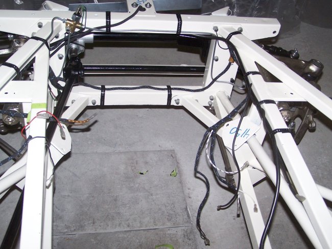
 39) The wiring for the bonnet plug is strapped to the bonnet frame as shown here. Care must be take to ensure that enough of the wire is loose so
that the plug will reach the socket on the bonnet.
39) The wiring for the bonnet plug is strapped to the bonnet frame as shown here. Care must be take to ensure that enough of the wire is loose so
that the plug will reach the socket on the bonnet.
|
 40) With the wiring installed, lots of firewall components can be installed. The clutch line is worth noting here. 3.8 liter Series I E-types had the
clutch lines mounted in-board of the left engine frame. The lines would then route under the clutch master cylinder and then loop around to the top.
Later on, the lines went across the top of the left engine frame and mounted to the clutch master cylinder from the top.
40) With the wiring installed, lots of firewall components can be installed. The clutch line is worth noting here. 3.8 liter Series I E-types had the
clutch lines mounted in-board of the left engine frame. The lines would then route under the clutch master cylinder and then loop around to the top.
Later on, the lines went across the top of the left engine frame and mounted to the clutch master cylinder from the top.
|
|
 28) The heater pipes are installed inside the cowl and are quite tricky to install. The first one to be installed is the long bottom
one. From inside the car the bottom center side goes in first, but will not go into position correctly. The left side must be
inserted inside the cowl, raised as high gas possible and be pulled up and to the left as much as possible. This allows the opposite
side to drop down below an inner cowl reenforcement. Then both ends may be pushed out the holes in the firewall. If the heater pipes are new, they
not want to pull through. So some force or pre-filing may be required.
28) The heater pipes are installed inside the cowl and are quite tricky to install. The first one to be installed is the long bottom
one. From inside the car the bottom center side goes in first, but will not go into position correctly. The left side must be
inserted inside the cowl, raised as high gas possible and be pulled up and to the left as much as possible. This allows the opposite
side to drop down below an inner cowl reenforcement. Then both ends may be pushed out the holes in the firewall. If the heater pipes are new, they
not want to pull through. So some force or pre-filing may be required.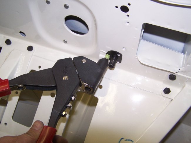 29) Collars are slipped over the end of the pipes and are pop-riveted in place. Standard pop-rivet guns will not reach, so the simplest solution
is to create a stack of small nuts and use them as a spacer, as shown here. The remainding heater pipes go in a lot easier.
29) Collars are slipped over the end of the pipes and are pop-riveted in place. Standard pop-rivet guns will not reach, so the simplest solution
is to create a stack of small nuts and use them as a spacer, as shown here. The remainding heater pipes go in a lot easier.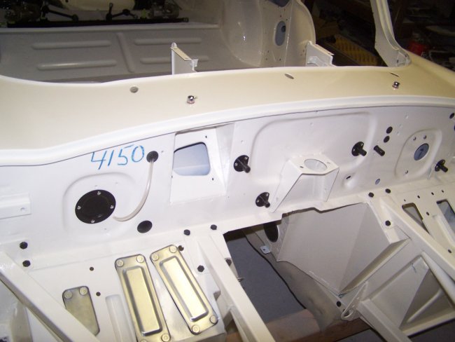 30) The washer jets install rather easily. The question is, do they both point outboard, do the both point inboard, do they both point to the
left or to the right? Which way the squirters point seems too depend the the jets themselves. The squirters just thread
into the base. They are then adjusted/turned up or down depending on where you want the fluid to hit the windshield. In this case both jets
had to be pointed to the left of the car so that the squirters would not be too loose to stay in place.
30) The washer jets install rather easily. The question is, do they both point outboard, do the both point inboard, do they both point to the
left or to the right? Which way the squirters point seems too depend the the jets themselves. The squirters just thread
into the base. They are then adjusted/turned up or down depending on where you want the fluid to hit the windshield. In this case both jets
had to be pointed to the left of the car so that the squirters would not be too loose to stay in place. 31) The fluid lines meet at a "T" fitting inside the cowl and are held in place with a PVC sleeved metal tab.
  34) Continuing on, the cooling fan needs to be installed prior to the brake lines because the wires for the fan go under the brake lines. The fan
is simply mounted on the front of the picture frame.
34) Continuing on, the cooling fan needs to be installed prior to the brake lines because the wires for the fan go under the brake lines. The fan
is simply mounted on the front of the picture frame.  35) The Brake lines meet at a junction block at the picture frame. The junction block is mounted at an angle with a brake pressure sensor screwed into it.
The brake lines need to be installed and adjusted/bent, prior to tightening the nut that holds the junction block in place.
35) The Brake lines meet at a junction block at the picture frame. The junction block is mounted at an angle with a brake pressure sensor screwed into it.
The brake lines need to be installed and adjusted/bent, prior to tightening the nut that holds the junction block in place.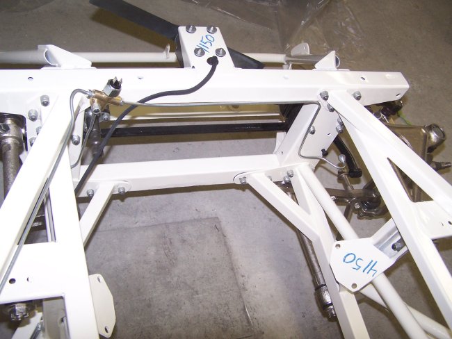 36) The front brakes lines are routed above and around the picture frame as pictured. The wires for the cooling fan go behind the brake line as shown. There
should be enough spacing to prevent the wires from being crushed.
36) The front brakes lines are routed above and around the picture frame as pictured. The wires for the cooling fan go behind the brake line as shown. There
should be enough spacing to prevent the wires from being crushed.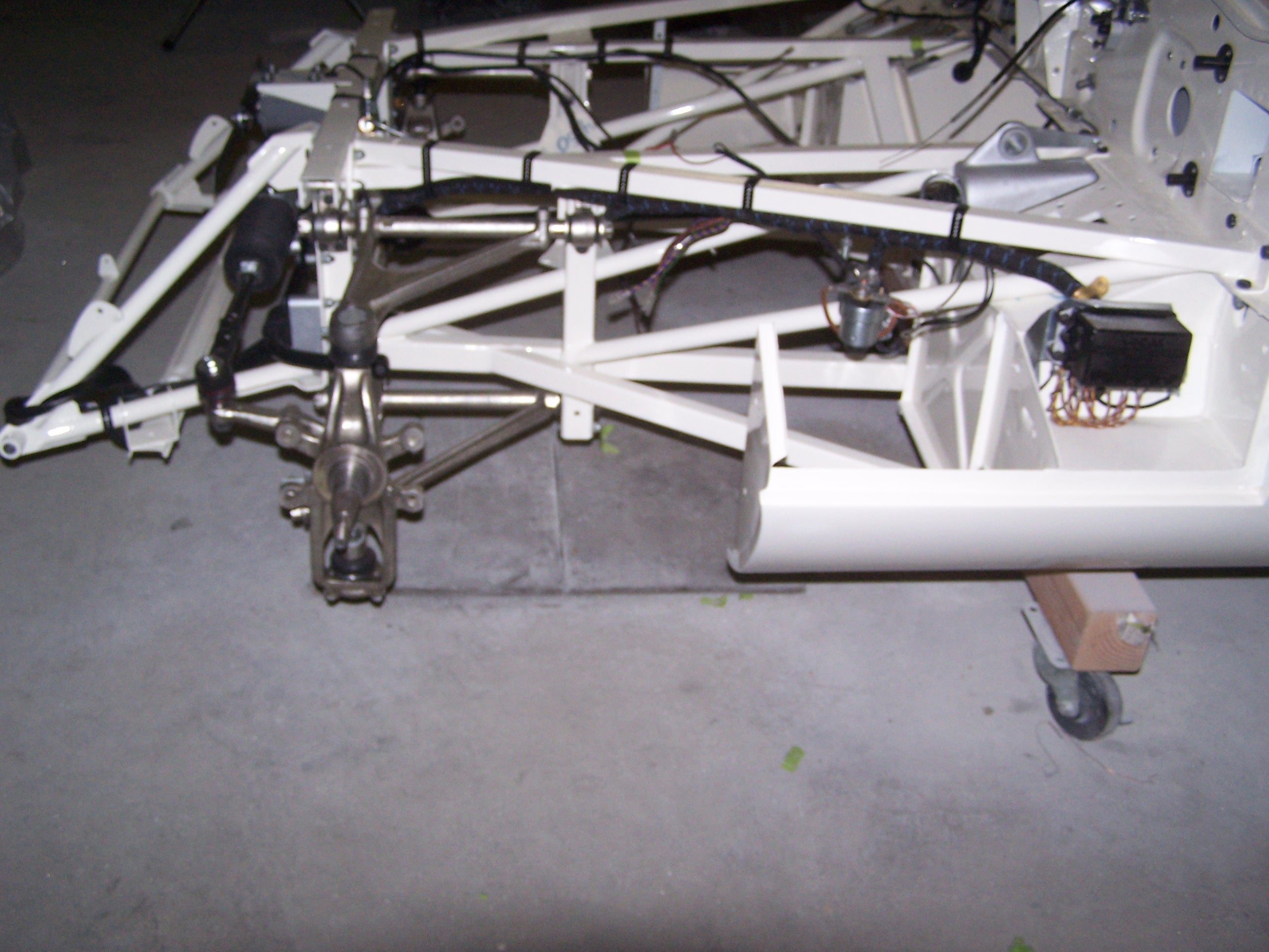 37) The main engine harness is rounted from the outside into the car behind the voltage regulator. A rubber grommet is slipped over the harness
and is inserted in the hole behind the voltage regulator. It should be noted that new grommets for this location are not available.
37) The main engine harness is rounted from the outside into the car behind the voltage regulator. A rubber grommet is slipped over the harness
and is inserted in the hole behind the voltage regulator. It should be noted that new grommets for this location are not available.
 38) The starter wire must be routed with the engine harness. The wire for the oil pressure sending unit is wrapped a few times around the
starter wire (right side of picture). The wiring and brake lines are held in place with plastic strapping which is readily available
through the typical Jaguar parts suppliers. Critical restorers may be interested in the fact that the pins for the straps were originally white
while the repos are black.
38) The starter wire must be routed with the engine harness. The wire for the oil pressure sending unit is wrapped a few times around the
starter wire (right side of picture). The wiring and brake lines are held in place with plastic strapping which is readily available
through the typical Jaguar parts suppliers. Critical restorers may be interested in the fact that the pins for the straps were originally white
while the repos are black. 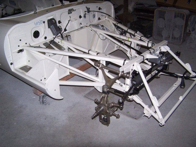 39) The wiring for the bonnet plug is strapped to the bonnet frame as shown here. Care must be take to ensure that enough of the wire is loose so
that the plug will reach the socket on the bonnet.
39) The wiring for the bonnet plug is strapped to the bonnet frame as shown here. Care must be take to ensure that enough of the wire is loose so
that the plug will reach the socket on the bonnet. 40) With the wiring installed, lots of firewall components can be installed. The clutch line is worth noting here. 3.8 liter Series I E-types had the
clutch lines mounted in-board of the left engine frame. The lines would then route under the clutch master cylinder and then loop around to the top.
Later on, the lines went across the top of the left engine frame and mounted to the clutch master cylinder from the top.
40) With the wiring installed, lots of firewall components can be installed. The clutch line is worth noting here. 3.8 liter Series I E-types had the
clutch lines mounted in-board of the left engine frame. The lines would then route under the clutch master cylinder and then loop around to the top.
Later on, the lines went across the top of the left engine frame and mounted to the clutch master cylinder from the top.