 19) The upper wishbone bolts easily in place. As with the lower wishbone, the pivot nuts should be tighten in order for the holes to line
up.
19) The upper wishbone bolts easily in place. As with the lower wishbone, the pivot nuts should be tighten in order for the holes to line
up.
|
 20) The rear upper wishbone bolts go through the engine frames where they are secured with nylock nuts and a reenforcement plate. Shims (not shown)
are inserted between the upper wishbone bracket and the face of the engine frame.
20) The rear upper wishbone bolts go through the engine frames where they are secured with nylock nuts and a reenforcement plate. Shims (not shown)
are inserted between the upper wishbone bracket and the face of the engine frame.
|
 21) On this car there was originally a 0.010" shim inserted at the front and rear of each upper wishbone. Also there was one unusually large 0.250"
installed at the right front upper wishbone. Original thickness shims should be installed during reassembly as a starting point for the front-end
alignment.
21) On this car there was originally a 0.010" shim inserted at the front and rear of each upper wishbone. Also there was one unusually large 0.250"
installed at the right front upper wishbone. Original thickness shims should be installed during reassembly as a starting point for the front-end
alignment.
|
 22) The stub axle carriers are the next parts to go on. However, only one balljoint should be tightened. This is necessary in order to install and
adjust the torsion bars.
22) The stub axle carriers are the next parts to go on. However, only one balljoint should be tightened. This is necessary in order to install and
adjust the torsion bars.
|
|
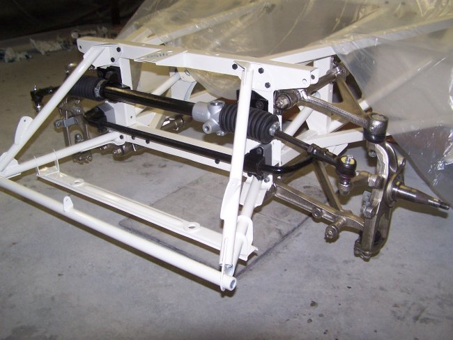
 23) The steering rack is the next thing to go on. It can installed as a single piece, with the mounts installed on the rack. Or the mounts can be installed
on the picture frame first.
23) The steering rack is the next thing to go on. It can installed as a single piece, with the mounts installed on the rack. Or the mounts can be installed
on the picture frame first.
|
 24) It only takes 6 bolts to hold the entire steering rack in place. Care must be taken in order to not chip the paint when sliding the
rack inside the bonnet support frame. As with the stub axle carries, the tie-rod end ball joints should not bolted in until after the torsion
bars are installed and adjusted.
24) It only takes 6 bolts to hold the entire steering rack in place. Care must be taken in order to not chip the paint when sliding the
rack inside the bonnet support frame. As with the stub axle carries, the tie-rod end ball joints should not bolted in until after the torsion
bars are installed and adjusted.
|
 25) One thing to keep in mind when installing the steering rack is that the mounting hardware is different on either side of the rack. On the driver's side
a pair of spacers are used on the out board mounting bolts. This appears to be for stiffening of the mount.
25) One thing to keep in mind when installing the steering rack is that the mounting hardware is different on either side of the rack. On the driver's side
a pair of spacers are used on the out board mounting bolts. This appears to be for stiffening of the mount.
|
 26) On the passenger's side, instead of spacers a pair of nuts are used. In this picture only the bottom nut can be seen.
|
|
 19) The upper wishbone bolts easily in place. As with the lower wishbone, the pivot nuts should be tighten in order for the holes to line
up.
19) The upper wishbone bolts easily in place. As with the lower wishbone, the pivot nuts should be tighten in order for the holes to line
up.
 20) The rear upper wishbone bolts go through the engine frames where they are secured with nylock nuts and a reenforcement plate. Shims (not shown)
are inserted between the upper wishbone bracket and the face of the engine frame.
20) The rear upper wishbone bolts go through the engine frames where they are secured with nylock nuts and a reenforcement plate. Shims (not shown)
are inserted between the upper wishbone bracket and the face of the engine frame.
 21) On this car there was originally a 0.010" shim inserted at the front and rear of each upper wishbone. Also there was one unusually large 0.250"
installed at the right front upper wishbone. Original thickness shims should be installed during reassembly as a starting point for the front-end
alignment.
21) On this car there was originally a 0.010" shim inserted at the front and rear of each upper wishbone. Also there was one unusually large 0.250"
installed at the right front upper wishbone. Original thickness shims should be installed during reassembly as a starting point for the front-end
alignment. 22) The stub axle carriers are the next parts to go on. However, only one balljoint should be tightened. This is necessary in order to install and
adjust the torsion bars.
22) The stub axle carriers are the next parts to go on. However, only one balljoint should be tightened. This is necessary in order to install and
adjust the torsion bars.
 23) The steering rack is the next thing to go on. It can installed as a single piece, with the mounts installed on the rack. Or the mounts can be installed
on the picture frame first.
23) The steering rack is the next thing to go on. It can installed as a single piece, with the mounts installed on the rack. Or the mounts can be installed
on the picture frame first.
 24) It only takes 6 bolts to hold the entire steering rack in place. Care must be taken in order to not chip the paint when sliding the
rack inside the bonnet support frame. As with the stub axle carries, the tie-rod end ball joints should not bolted in until after the torsion
bars are installed and adjusted.
24) It only takes 6 bolts to hold the entire steering rack in place. Care must be taken in order to not chip the paint when sliding the
rack inside the bonnet support frame. As with the stub axle carries, the tie-rod end ball joints should not bolted in until after the torsion
bars are installed and adjusted.  25) One thing to keep in mind when installing the steering rack is that the mounting hardware is different on either side of the rack. On the driver's side
a pair of spacers are used on the out board mounting bolts. This appears to be for stiffening of the mount.
25) One thing to keep in mind when installing the steering rack is that the mounting hardware is different on either side of the rack. On the driver's side
a pair of spacers are used on the out board mounting bolts. This appears to be for stiffening of the mount. 26) On the passenger's side, instead of spacers a pair of nuts are used. In this picture only the bottom nut can be seen.