|
|
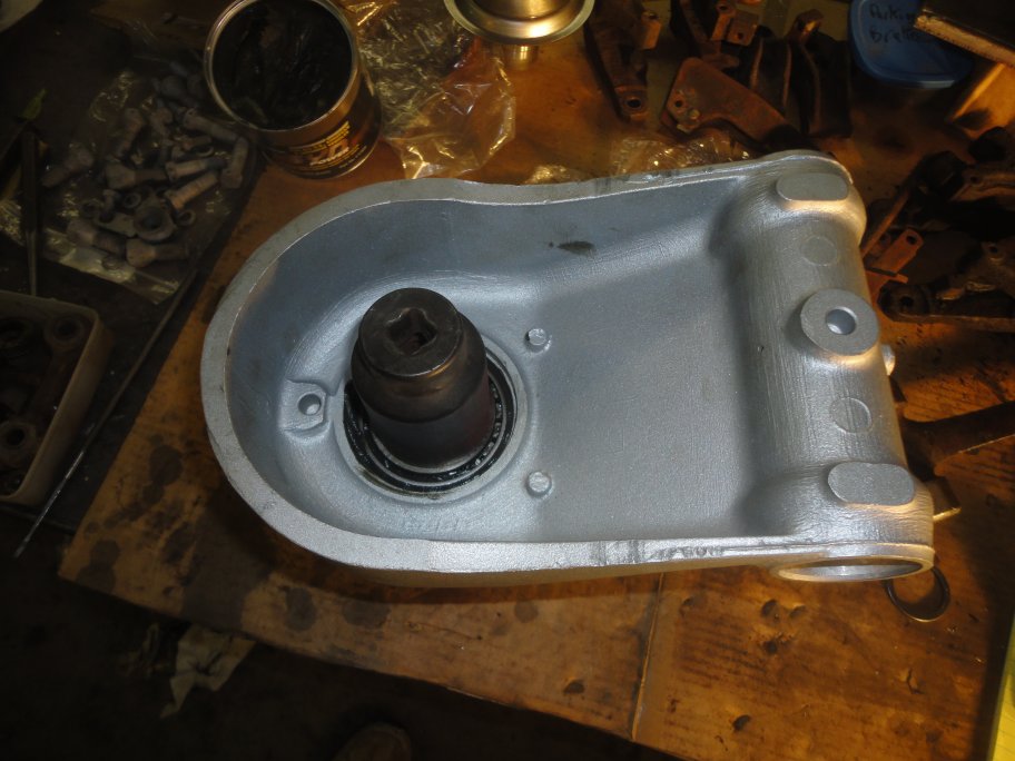 9) This is where the assembly becomes tricky. The inboard inner bearing needs to be installed. According to the service manual you need to create a special adaptor that has a 0.150" step on it. You are supposed to drive or press the bearing in with the adaptor, which will result in a very large float/endplay in the bearings. You are supposed to measure the float that is produced and the shim thickness required to give you about 0.005" worth of float. Since I could not or did not want to create the special adaptor I did things a different way.
I used a large socket and a hammer to drive the inner bearing onto the end of the hub assembly (though I could have used a driveshaft yoke and drawn it in). I drove it on enough to produce roughly 0.020" worth of bearing float. (too little and I would have had to press the bearings back out and start over). It should be noted the end of the inner hub is actually too short to go all the way through the bearing. It is in fact roughly 0.150" too short.
|
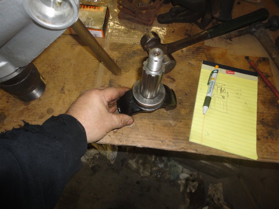 10) The next step is to measure the bearing float. I found this easier to accomplish by installing the splined yoke (seen here) for the measurement. In this picture you can see a sketch I made while trying to understand the procedure in the service manual. The special adaptor with the 0.150" step is at the top.
|
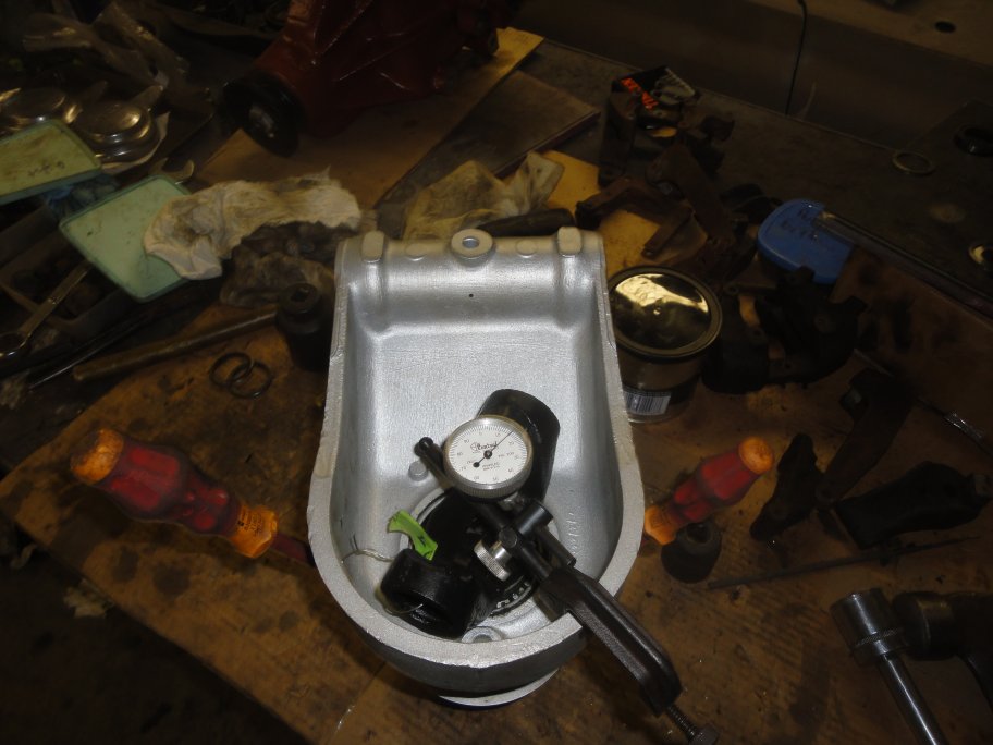 11) A dial indicator is mounted to the hub housing and the pin is set to contact the yoke. Note: In this picture the dial indicator was adjusted to read the float measurement that I had previously taken (0.015"). This is just the way I like to verify my readings. Normally it should be set to zero.
|
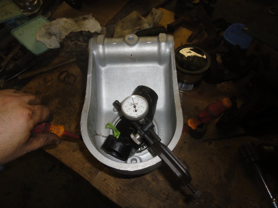 12) Using a pair of flat blade screw drivers, you pry between the water-thrower and the hub housing evenly and take the reading. You need to take several readings to make sure that the reading is accurate. This picture was taken immediately after the previous one, but with pressure applied. The reading of 0.000" indicates that my float was indeed 0.015".
|
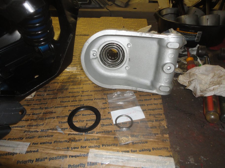 13) The next step is to measure the distance between the inner bearing face and the end of the inner hub. If I had made the special adaptor it would have been 0.150". I don't have pictures of how the measurement was made. I set the assembly on a flat stone at work in our QC department. I used a dial indicator to measure the location of the two surfaces and calculated the difference. On the hub assembly in this picture sequence, I had measured 0.134".
A spacer is used to set the final bearing float. The ideal float is 0.005". The ideal spacer required to achieve the float for this hub assembly is: 0.134" + 0.015" - 0.005" = 0.144". Spacers are available in different incremental sizes. For this hub asby I had to purchase a 0.144" spacer. When the spacer is installed and the yoke nut is torqued down the inner bearings will be drawn together and will produce a float of 0.005".
This picture shows the new spacer and the inner bearing seal ready for installation.
|
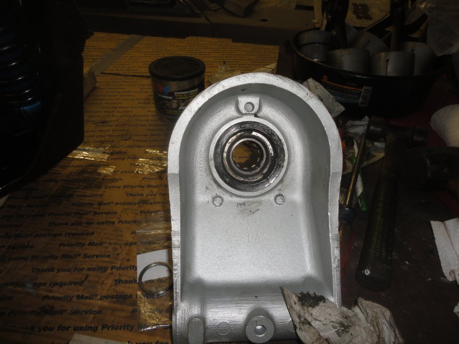 14) The seal is easily installed with a rubber mallet. The lip of the seal and back face are given a thin coat of grease. The new spacer is not installed at this time, but it is a good idea to keep it with the intended hub assembly since it is most likely that both hub assemblies will require different spacers.
|