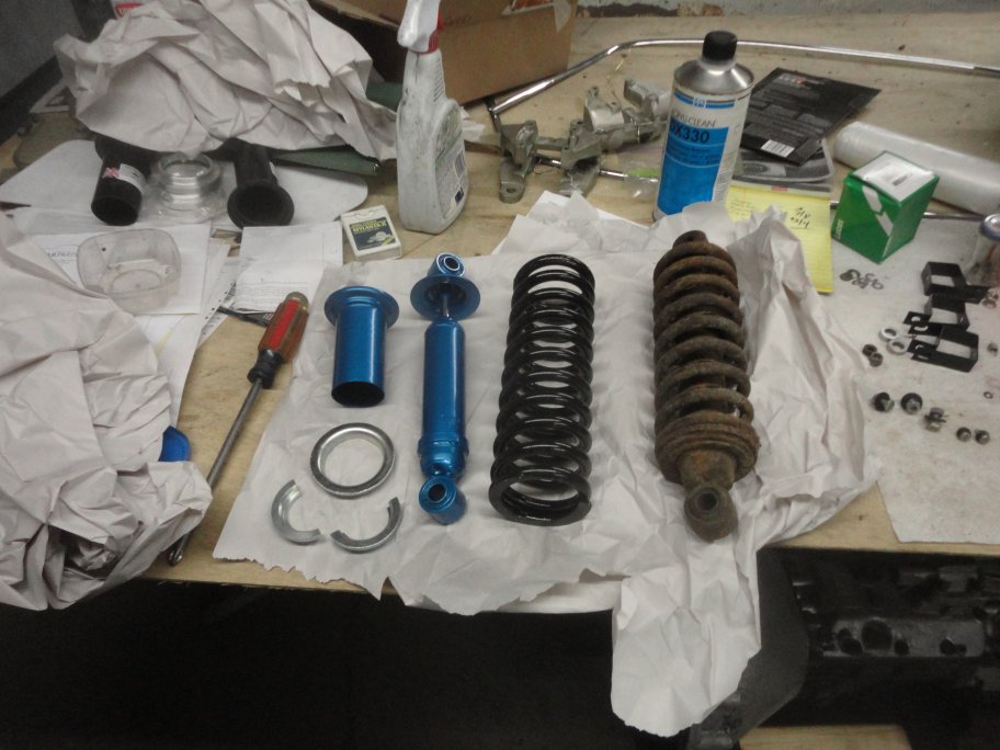
 1) For the rear shocks there is no point in saving any of the original components unless they are in really nice shape. Every piece can be bought new. All you have to do is put them together. Original Girling brand shocks are not available, but the Boge aftermarket shocks are really close in appearance. If you cannot save the original dust shields from the original shocks, repos are available.
|
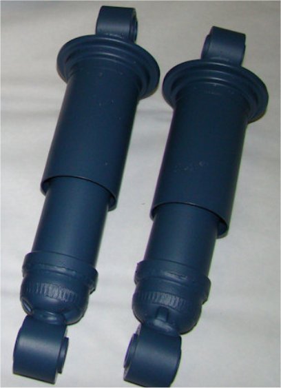 2) Here is a picture of what a professionally restored set of original Girling shocks look like in the correct Girling Blue. The original colored paint can't be bought from the Jaguar part suppliers. So without an original shock with color available for computer matching, you are on your own as far as color.
|
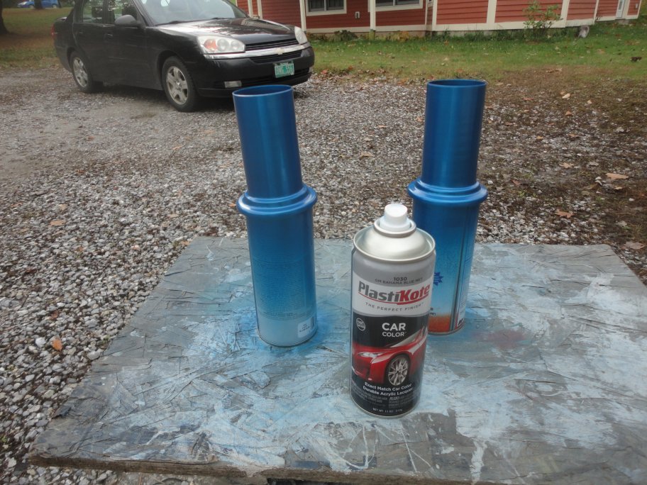 3) The closest color I found in an off-the-shelf rattle can came really close to the replacement Girling shock color. Concourse judges do not judge shoke color (at least not on the Jags), so I went with a replacement shock color.
|
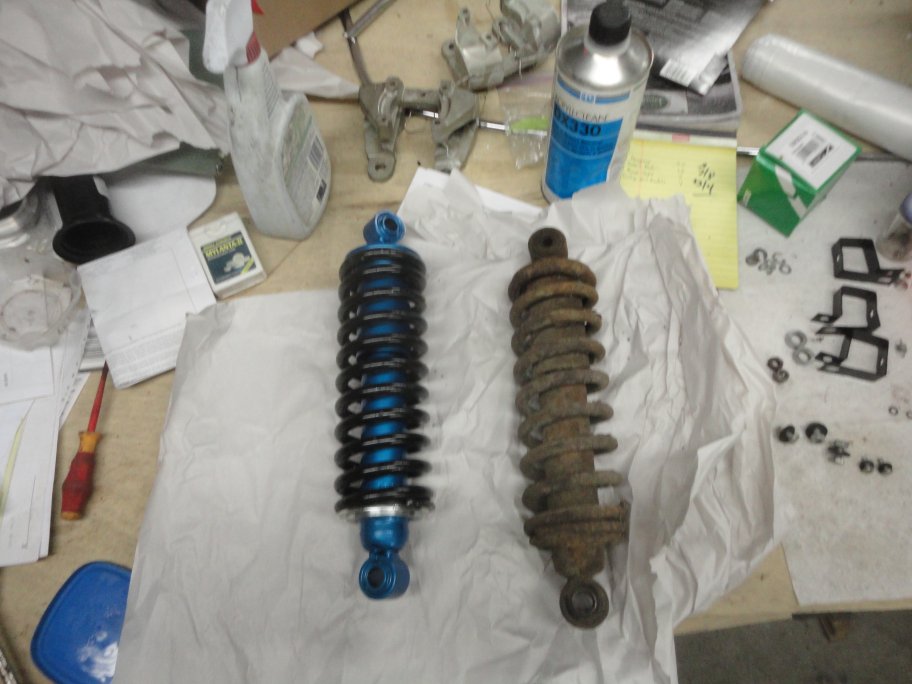 4) Here is an assembled shock next to an original one.
|
 5) There are a few tricks to assemble the shocks. Some people use two brake rotors with two threaded rods to compress the spring. I prefered to use my press with my bearing puller. The rear springs are held in place in a very similar manner as an intake and exhaust valve. A collar is set on top of the spring which is then compressed. A two piece inner collar is dropped in place and the tension is released.
I was a little nervous about how well things were being held in the press so I opted to use a magnet on a rod to place the inner collar just in case it all let go.
|
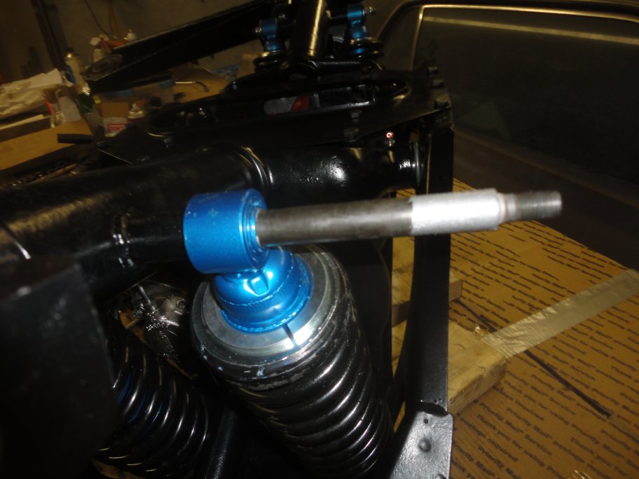 6) A pivot shafts are used to retain the shocks to the lower control arms. Anti-Seize grease should be used to keep the parts from wearing and to enable easy disassembly in the future.
|
|
|
|
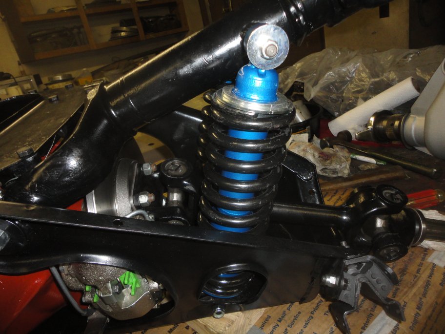 7) The shocks bolt to the top of the cage from the inside out. If the bolts were inserted from the outside, it would be impossible to removed the shocks without pullinf the IRS.
|
 8) The radius arms need to be installed prior to the hub assemblies. Each radius arm has two bushings that need to be replaced using a press.
|
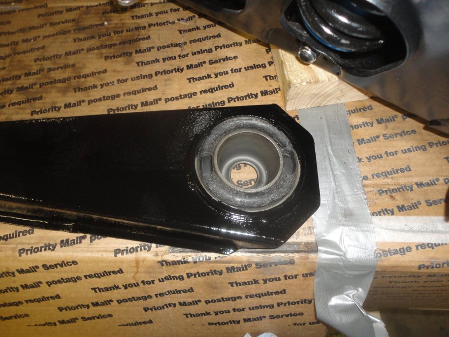 9) The larger of the two bushings needs to be installed in a specific orientation. No reason is given in the manuals, but it appears that the cut-outs need to be towards the front and the rear so that there is enough give to the bushing when the wheels are not touching the ground. Otherwise the inner metal cup would want to break free of the rubber.
I was lucky enough to get a pair of original large Metalastic bushings, which are no longer available.
|
 10) The radius arms are bolted to the lower control arms with special low-profile bolts. The low-profile is needed so that the hub assembly clears the bolt head. As usual, anti-seize grease should be used.
|
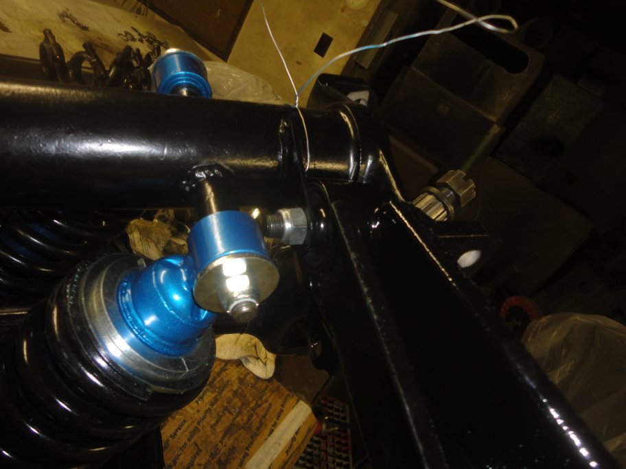 11) The radius arms are attached with a nyloc nut from the inside.
|
|