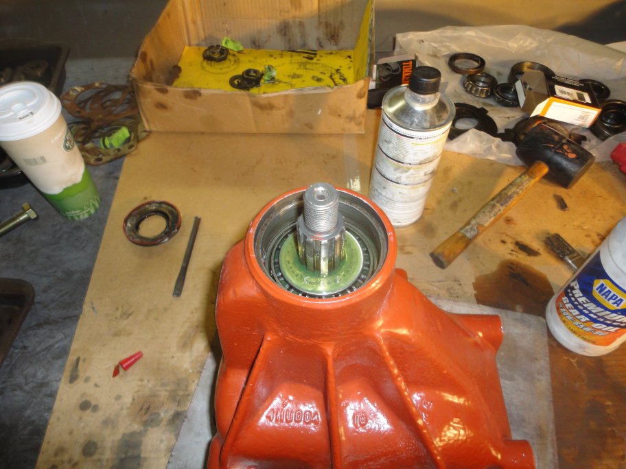
 1) When it came time to put the differential back together, the first thing you may notice is that I didn't do something. I didn't
replace the pinion bearing. This was a conscience choice based on the condition of the bearing and by the difficulty of setting the
pinion in place. So unfortunately you will have to go to the service manual for proper instructions.
Here it is in a nutshell. You have to press the pinion out, which removes the inner bearing at the same time. You then have to drive
the outer race of the pinion bearing out of the differential housing. You then must install the new outer race into the differential
housing. This is where it gets fun: You have to install the pinion in the differential housing from the inside and place the new inner
bearing on the pinion from the outside. You have to draw the inner bearing in using a spacer and a nut. You must use a dial indicator mounted inside
the differential housing to set the depth of the pinion. If you do this operation wrong, the pinion and crown grear will not meet correctly
and you have to press the pinion out and start over. Glad I didn't have to do this operation.
In my case, with the pinion bearing cleaned in inspected, I first lubricated the bearing with 90W gear oil.
|
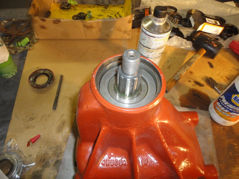 2) Next goes in the oil deflector which just drops in place.
|
 3) Which is then followed by a seal.
|
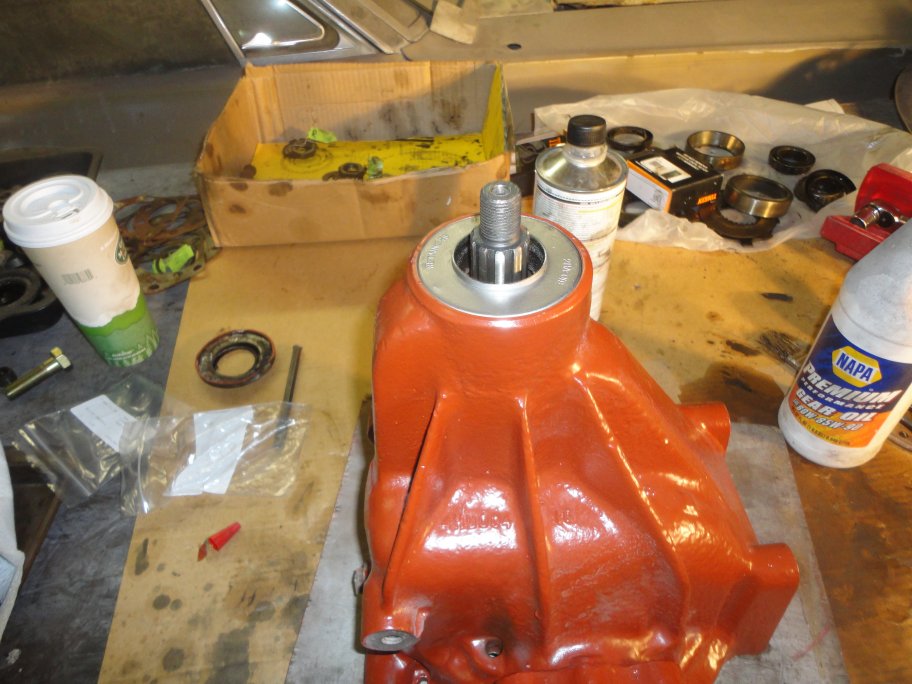 4) Which in-turn is followed by the outer seal. Though not shown, the propeller shaft flange goes on last. The seal and the shaft should
receive a thin coat of grease before they go together.
|
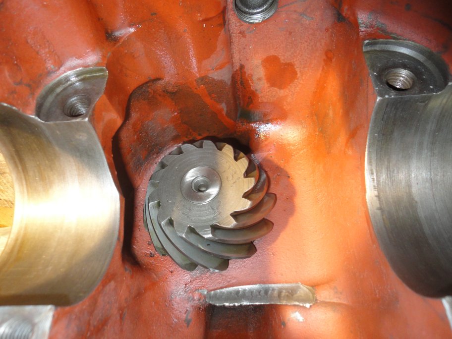 5) On this pinion 2731 is carved into it which matched the 2731 carved into the crown gear. Also carved into the pinion is a "+12". This is what the
backlash must be set to. Some people may disagree with that statement, but I checked how my gears overlap after the adjustment and they were perfectly centered.
|
 6) To perform the backlash adjustment, first the carrier must be installed with the bearing caps barely tightened. The output shafts are installed WITHOUT
the shims that go between the diff housing and the output shaft brackets.
|
|
|
|
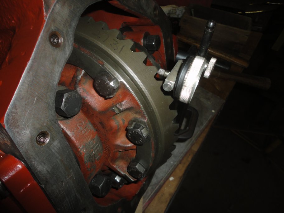 7) A dial indicator is setup contacting a tooth on the crown gear. The crown gear is
rotated back and forth between the points where the pinion and crown gears make contact from top to bottom.This slop is the "backlash" that needs to be set.
|
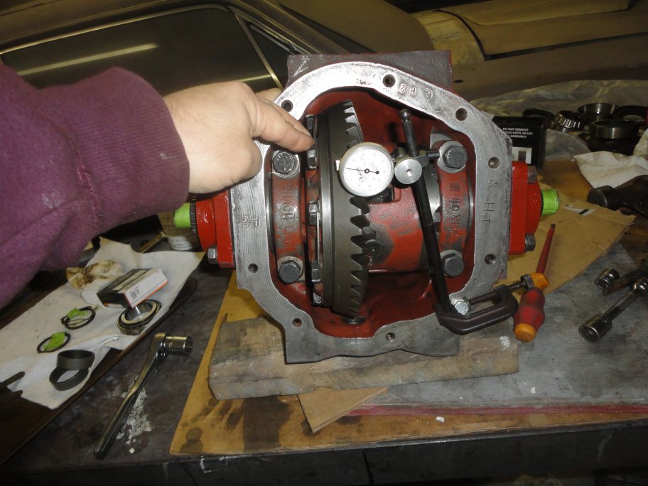 8) The left output shaft bolts are tightened little by little to drive the carrier and its bearings to the left, which reduces the backlash. You tighten the
output shaft bolts on the left to reduce the backlash measured by the dial indicator. You will need to loosen the bolts on the right output shaft bracket if
it is preventing the carrier bearings from shifting to the right.
Once you are confident that the backlash is set, the carrier bearing caps must be tightened down. This may throw the backlash adjustment off, so the backlash
may need to be adjusted again. This means the bearing caps have to be loosened again.
|
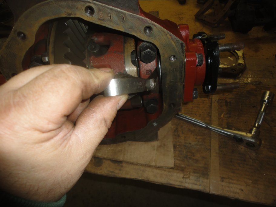 9) With the backlash set and the bearing caps tightened, the output shafts can be properly installed. Shims are used to prevent the output shaft brackets from contacting
the carrier bearings. The shims, pictured earlier, are not installed when performing the backlash adjustment.
The process is, you back the output shaft assemblies out (if they are still installed) so that the output shaft bracket clears the carrier bearings by a lot.
You bring in the output shaft bracket evenly by tightening the housing bolts so that the inner face of the output shaft bracket barely clears the carrier
bearing a specified amount (see service manual, yah I know, I should look it up and record it here). This picture shows the clearance measurement being made
with a feeler gauge. With the clearance obtained, you measure the gap between the output shaft bracket and the differential housing. This measurement yields what the
ideal shim thickness needs to be. However, the available shims will most likely not add up to what is needed, but the bearing clearance is not highly critical if you need to
go with a larger gap.
|
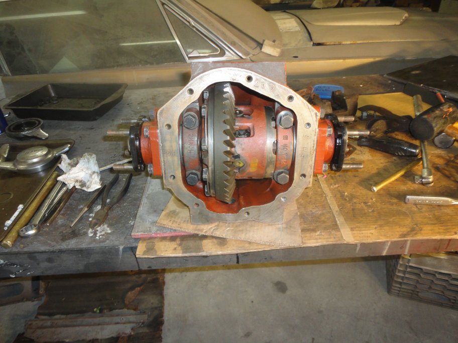 10) Here is the diffential all bolted together awaiting the rear cover.
|
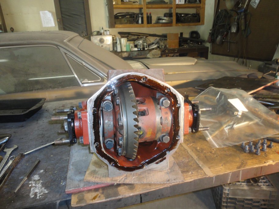 11) I use Indian Head Gasket Shellac Compound by Permatex on differential cover gaskets.
|
 12) Here's the differential cover installed. The vent cap is missing in this picture. All of the hardware is original. I replated the hardwre at home with my Caswell Zinc Plating kit
with blackoxidizer solution. The differential housing is painted with PPG DP74LF Red Oxide Primer, which I believe is a close approximation to what the original factory primer
was. The rear cover is semigloss black, though some restorers go full gloss on their black parts. As you can seen in this picture the rear face of the
differential housing is bare metal. This is what it looked like from the factory. The housing was primed then machined. At some point the bare metal will rust slightly. It's the
price you have to pay for a look of originality.
|
|