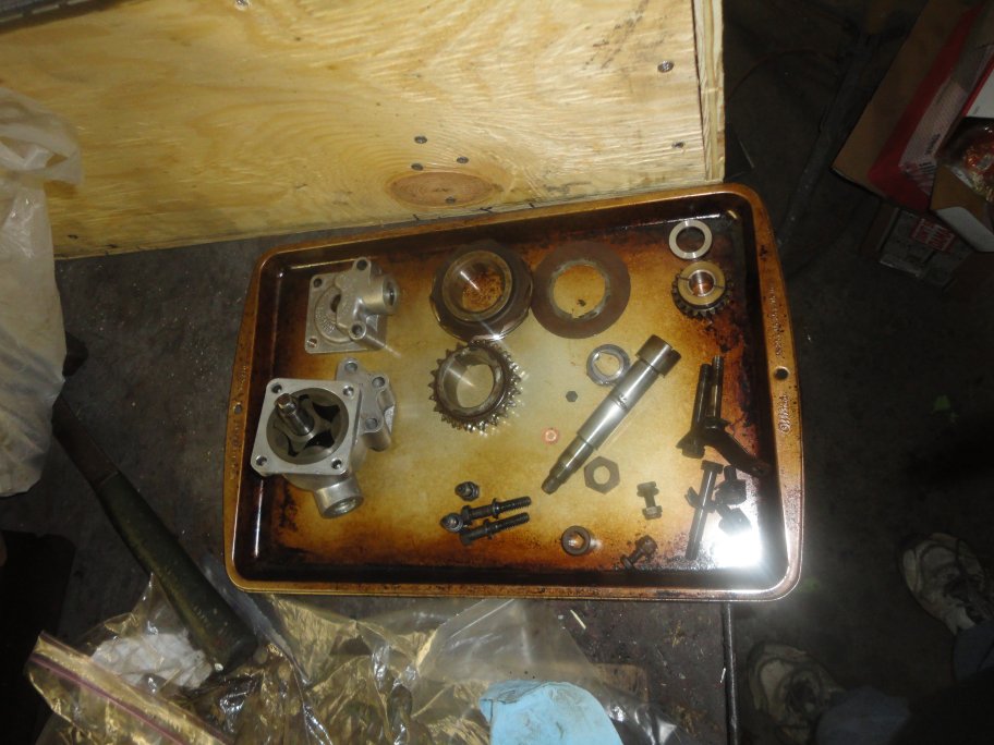
 28) Here are the components for the oil pump, distributor shaft and lowing timing gear after cleaning. The oil pump clearance
was measured and still appeared to be within the limits in the service manual so I opted not to replace it.
28) Here are the components for the oil pump, distributor shaft and lowing timing gear after cleaning. The oil pump clearance
was measured and still appeared to be within the limits in the service manual so I opted not to replace it. |
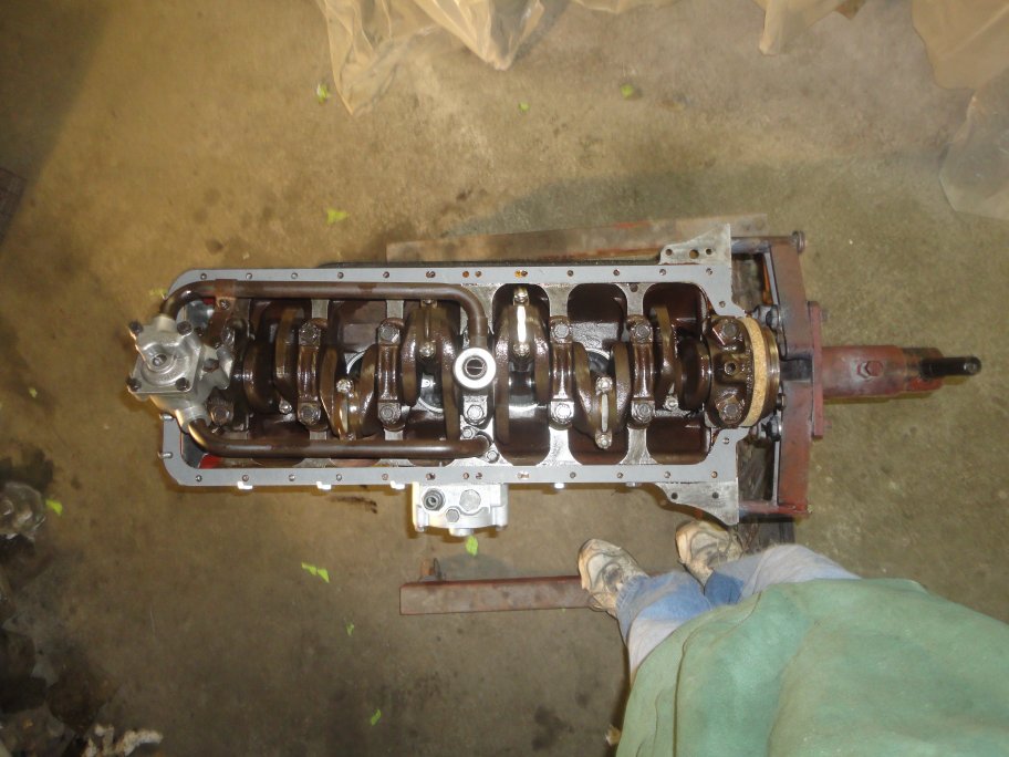
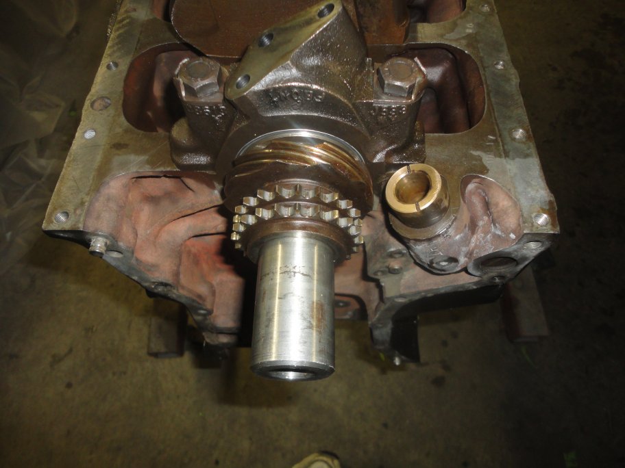 29) The timing and crank distributor gears go on first.In this picture the distributor shaft bearing is installed in the block. A single
bolt is used to keep the bushing from moving (not installed in this picture).
29) The timing and crank distributor gears go on first.In this picture the distributor shaft bearing is installed in the block. A single
bolt is used to keep the bushing from moving (not installed in this picture).
|
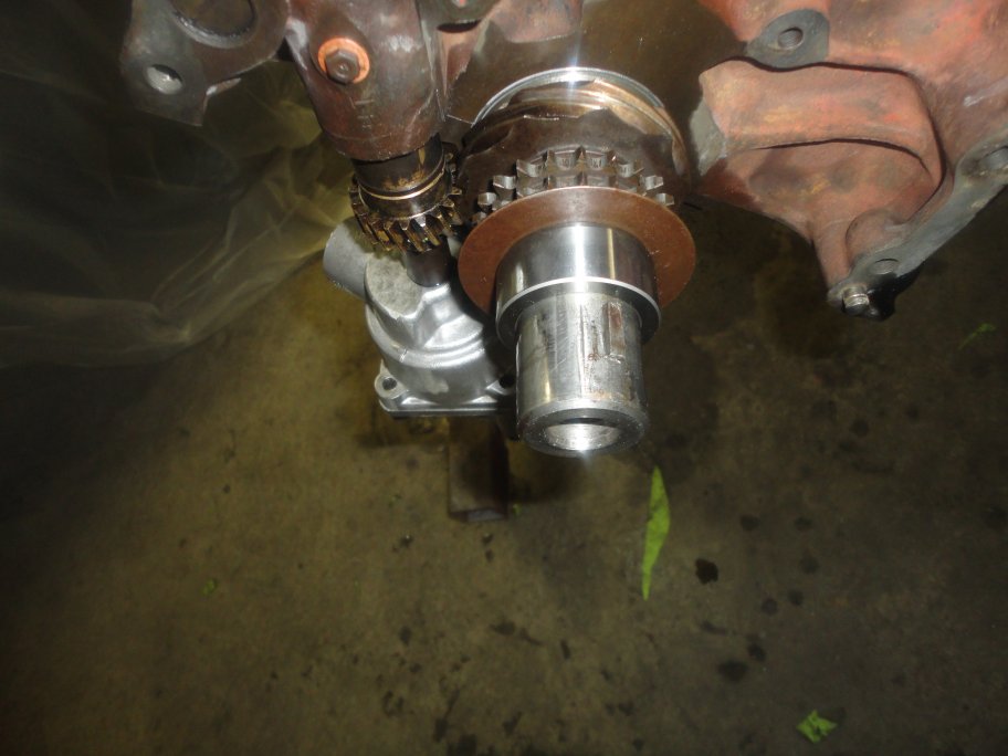
 30) The distributor shaft and shaft gear go on next. A nut holds it all together. A metal locking tab is bent over to prevent the nut from loosening.
|
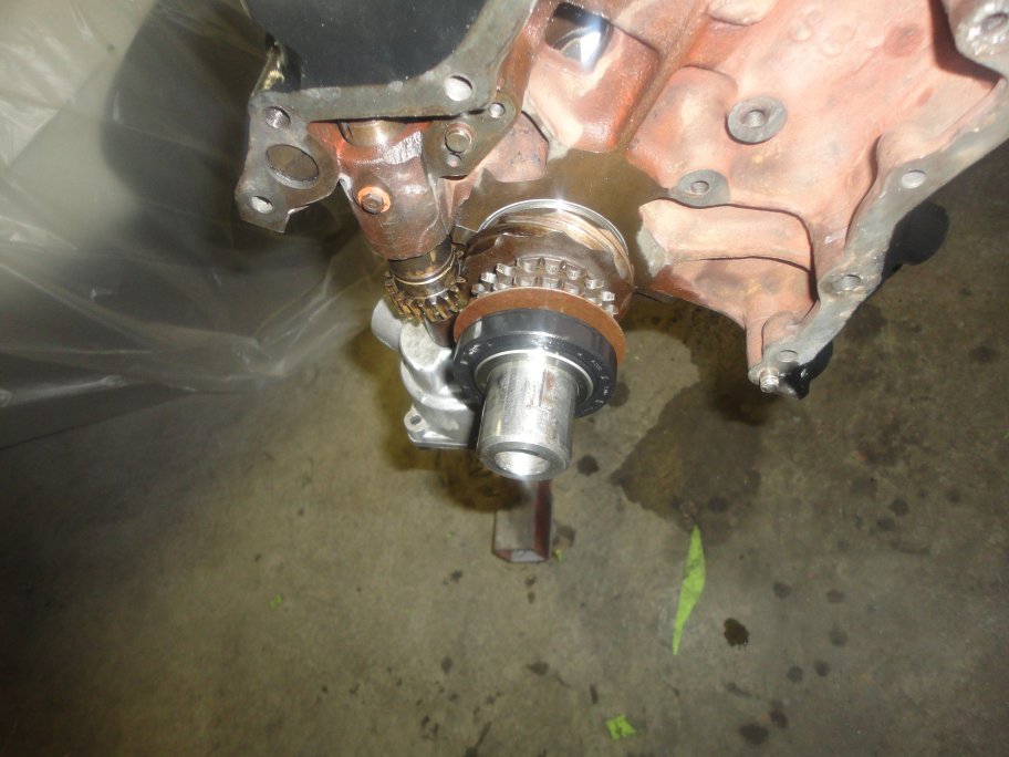
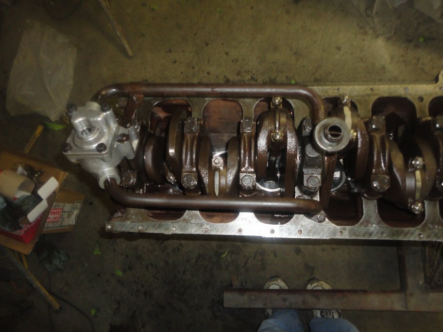 31) The oil pump is driven by the distributor shaft. Installation is straight forward.
|
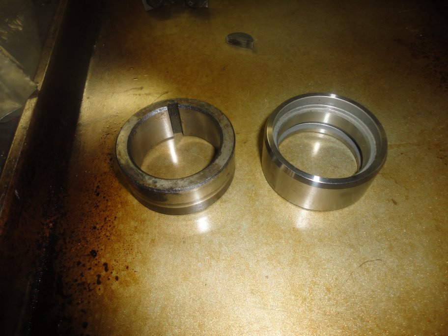 32) The new timing cover seal spacer that I recieved was different then the original one. It does not have a notch in it so it can not be installed without
removing the harmonic balancer's woodruff key from the end crank shaft.
32) The new timing cover seal spacer that I recieved was different then the original one. It does not have a notch in it so it can not be installed without
removing the harmonic balancer's woodruff key from the end crank shaft.
|
 33) Here it is in place with the harmonic balancer woodruff key installed.
|
 34) With oil applied to both mating surfaces the timing cover oil seal was fitted.
|
 35) I decided to coat the inside of the face of the block with glyptol since it did not look very sealed from the factory. Care was taken
as to not coat mating surfaces where the timing chain gears guides and cover attach.
35) I decided to coat the inside of the face of the block with glyptol since it did not look very sealed from the factory. Care was taken
as to not coat mating surfaces where the timing chain gears guides and cover attach.
|
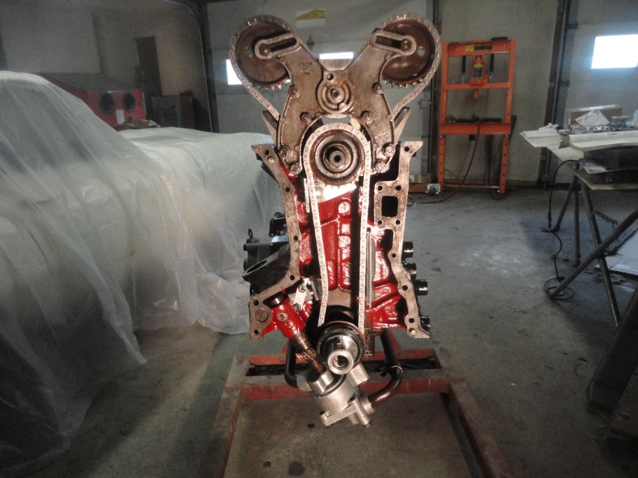 36) Installation of the timing chain and gears was relatively straight forward. I had to straighten one of the new guides (top left one)
in order to get it to align with the chain properly.The spring loaded chain tensioner (bottom left) was different then the original one.
The original one comes with a screw to lock it in place for installation. The new one doesn't. The spring needs to be compressed when installing it
(I assumed since it didn't come with any instrucitons). It barely wanted to stay compressed on its own do to the ratcheting mechanism inside.
I didn't trust it, so I held it as compressed as I could get it to install it.
It seamed to apply a suffient amount of tension on the chain. I hope I did it right.
36) Installation of the timing chain and gears was relatively straight forward. I had to straighten one of the new guides (top left one)
in order to get it to align with the chain properly.The spring loaded chain tensioner (bottom left) was different then the original one.
The original one comes with a screw to lock it in place for installation. The new one doesn't. The spring needs to be compressed when installing it
(I assumed since it didn't come with any instrucitons). It barely wanted to stay compressed on its own do to the ratcheting mechanism inside.
I didn't trust it, so I held it as compressed as I could get it to install it.
It seamed to apply a suffient amount of tension on the chain. I hope I did it right.
|
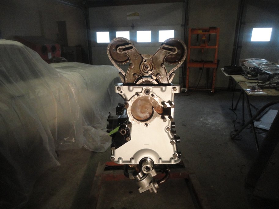 37) The timing cover went on rather uneventful. The upper right bolt (in this picture) is actually the mounting location for the generator bracket.
I used a spare bolt to tighten the cover down since I was not ready to install the bracket.
37) The timing cover went on rather uneventful. The upper right bolt (in this picture) is actually the mounting location for the generator bracket.
I used a spare bolt to tighten the cover down since I was not ready to install the bracket.
|
 38) The oil pan cleaned up rather nicely. All I did to dress it up was to soda blast the outside.
|
 39) Four new studs were used at the bottom of the timing cover. A coat of indian head gasket sealer was applied to the underside of the gasket
and the mating surface on the block before the gasker was installed.
39) Four new studs were used at the bottom of the timing cover. A coat of indian head gasket sealer was applied to the underside of the gasket
and the mating surface on the block before the gasker was installed.
|
 40) A cork gasket is used to seal oil pan at the rear main bearing cap. Sealant was only applied at the corners where the cork met the paper gasket.
|
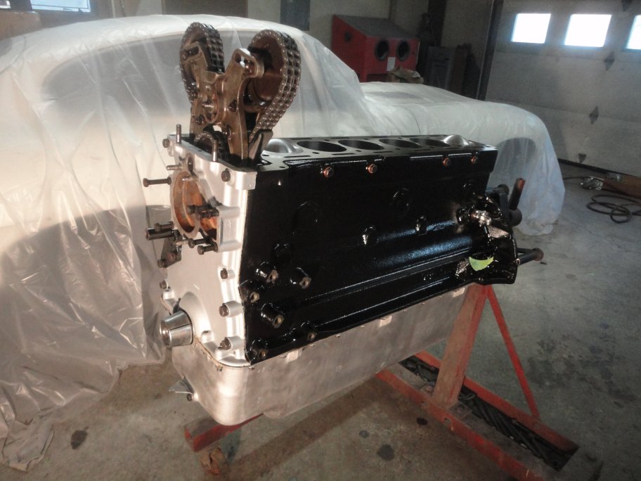 41) Here it is with the oil pan installed. Just a few items left before the head goes on.
|
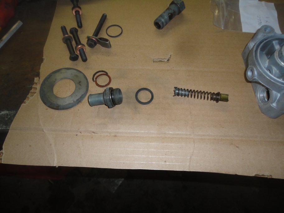 42) Here is the oil filter bracket and assiated components. All it really needed was some cleaning and new gaskets.
|
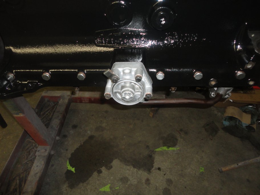 43) Here it is reassembled and installed. The bracket in the upper left hand corner (though it belongs on the bottom right corner) is used to capture
the carburator overflow pipes. It took me 5 years to discover what the bracket was for. The original overflow pipes were cut short and
I could not find a reference anywhere pertaining to the bracket. I just happened upon a picture on the web searching for something else. And now you know about it.
43) Here it is reassembled and installed. The bracket in the upper left hand corner (though it belongs on the bottom right corner) is used to capture
the carburator overflow pipes. It took me 5 years to discover what the bracket was for. The original overflow pipes were cut short and
I could not find a reference anywhere pertaining to the bracket. I just happened upon a picture on the web searching for something else. And now you know about it.
|
 44) The drain hose is simply attached with a couple cheney clamps.
|
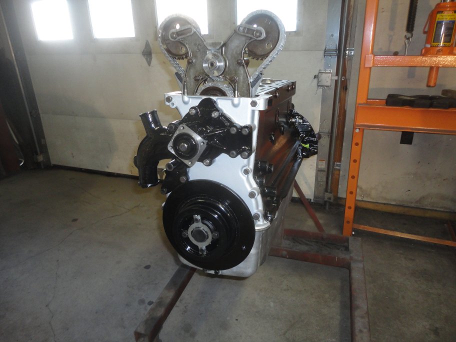 45) It's a simple matter to install the water pump and harmonic balancer. The new 2 groove crank pulley came in aluminum, but when it is painted black
you can't tell it from the original part once the engine is installed in the car.
45) It's a simple matter to install the water pump and harmonic balancer. The new 2 groove crank pulley came in aluminum, but when it is painted black
you can't tell it from the original part once the engine is installed in the car.
|
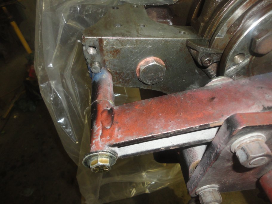 46) It's important not to overlook this plug before installing the flywheel.
|