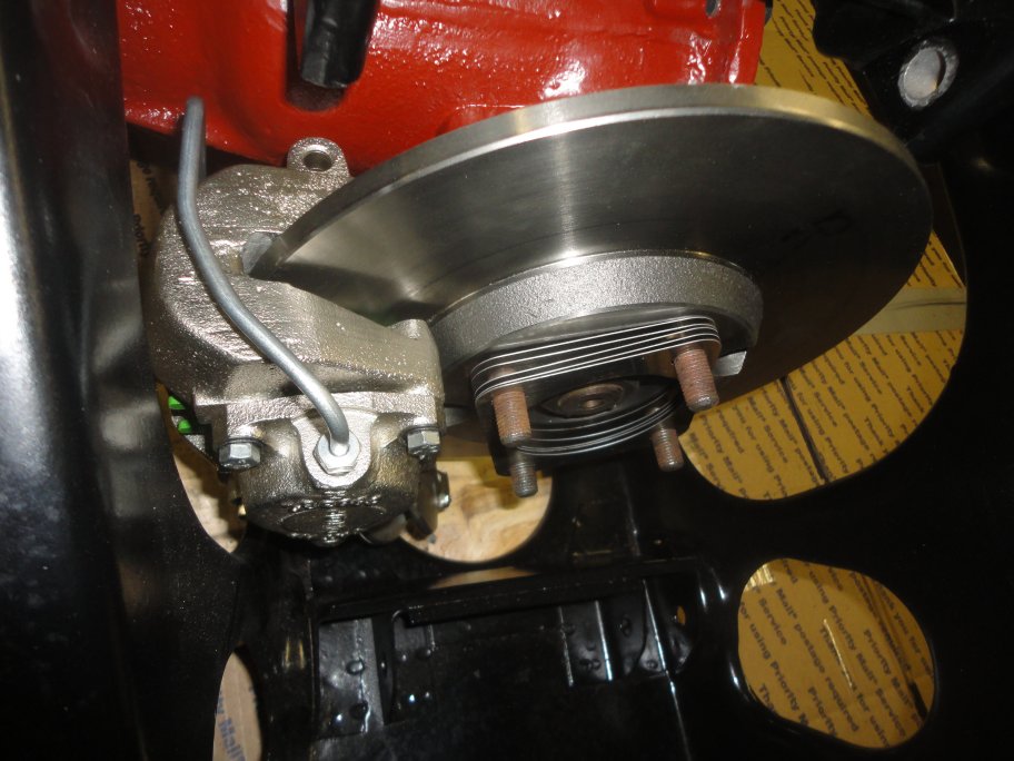
 1) It's easier to install the half drive shafts before installing the control arms. The rear wheel camber is set using shims between the rotor and the drive shafts. It's best to just replace the shims with new ones of the same thickness as a starting point. The camber will need to be fine tuned when the car is back together and on its road wheels. As you can see, setting the camber is not a fun activity.
|
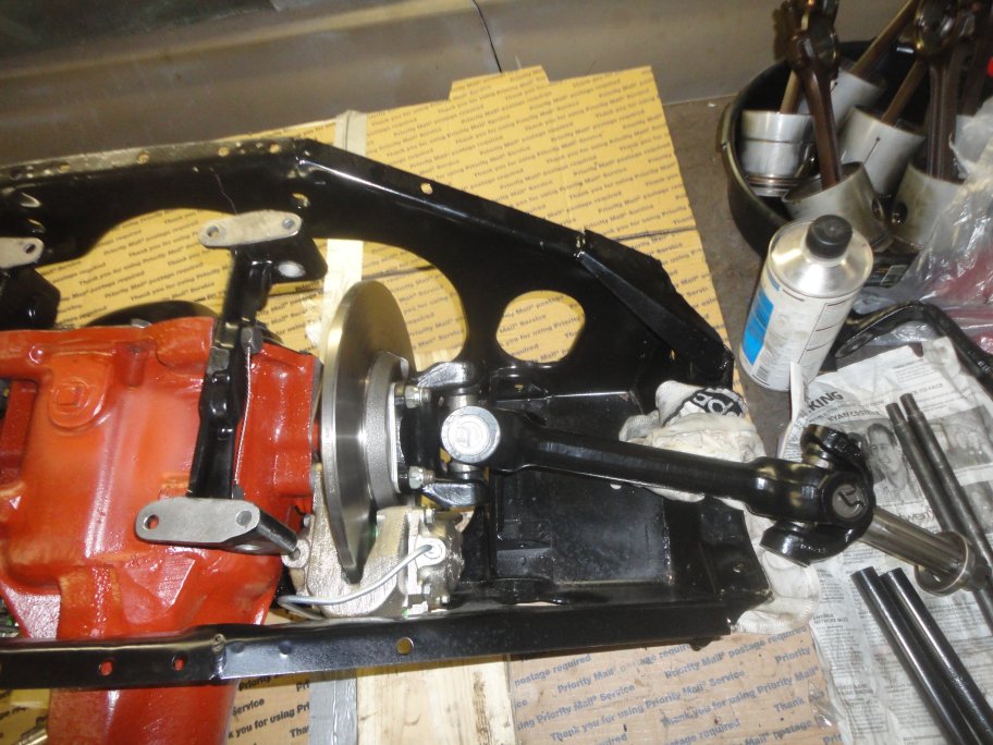 2) The half drive shafts are bolted in place using special locknuts. WARNING: Do not use nylocs. The heat from the brakes will cause the nylon to melt and the nuts will loosen up.
|
 3) New inner fulcrum bearings must installed on the lower control arms before installing the control arms. There are a few options available on the market. The original needle bearing style and a brass bushing. For this project I installed the original style bearings. With this style each end is comprised of two identical needle bearing sets and a spacer.
|
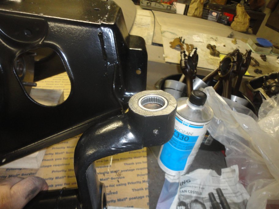 4) The outer needle bearings are installed first. They should be flush to the side face of the control arm. A hammer and a block of wood can be used for this operation.
|
 5) Next to go on is a spacer. Since it can rotate in the bore, a little grease to prevent wear is in order.
|
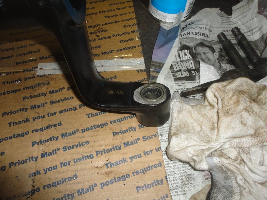 6) Then the inner bearing is installed. Again just with a block of wood and a hammer.
|
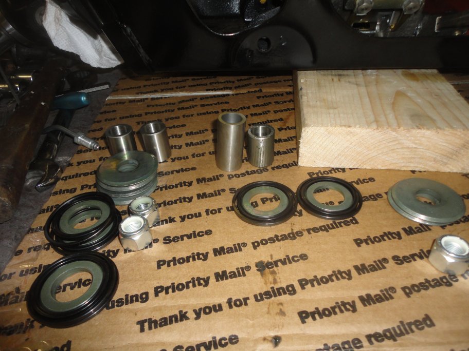 7) The spacers and grease rings for the inner fulcrum are comprised of a lot of pieces. However, once you put them together they are a little less imposing. It should be noted that earlier cars had longer inner bearing tubes (the tall one in this picture). Make sure you get the correct one (C17168) for your application.
|