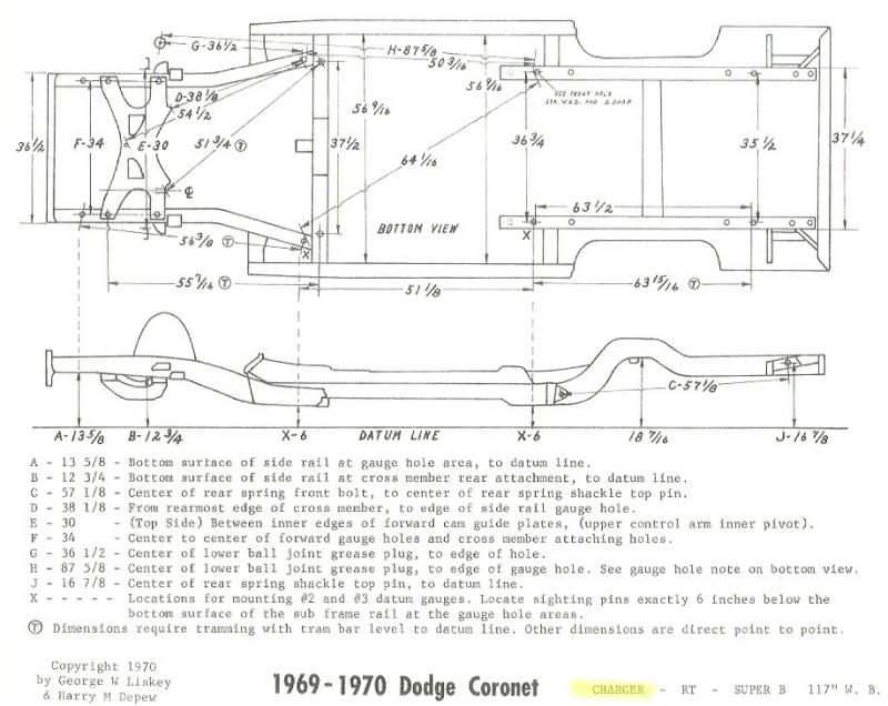
The drawing is a dimensionsal drawing for 1969-1970 B-Body Chryslers. Often refered to as the "crash sheet". It is intended to help collision repair shops straighten accident damaged cars. It gives dimensions based on original factory holes so the shop can hang their alignment gauges and take measurements while they straighten the body on a frame puller.
Before I built the jig I had to prepare the 4 frame rails.....
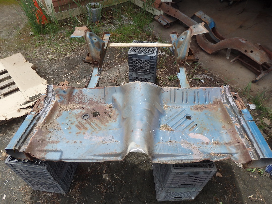 This front frame rail clip came with the car when I bought it.
 |
 As with any modern collision piece, I had to remove the unwanted metal by drilling and grinding the spotwelds.
 |
 Once the metal was cleaned up, I had it sandblasted and performed some minor rust repairs.
 |
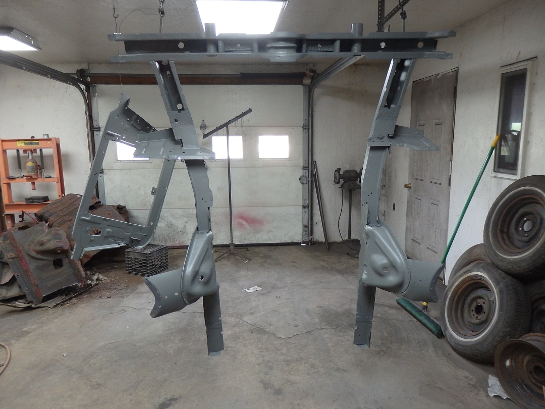
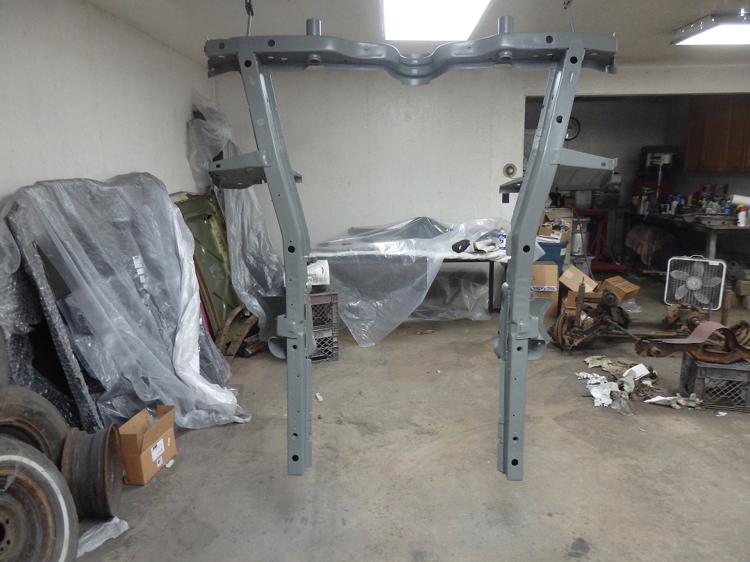 I then hung it from the garage ceiling and put it in epoxy primer.
 |
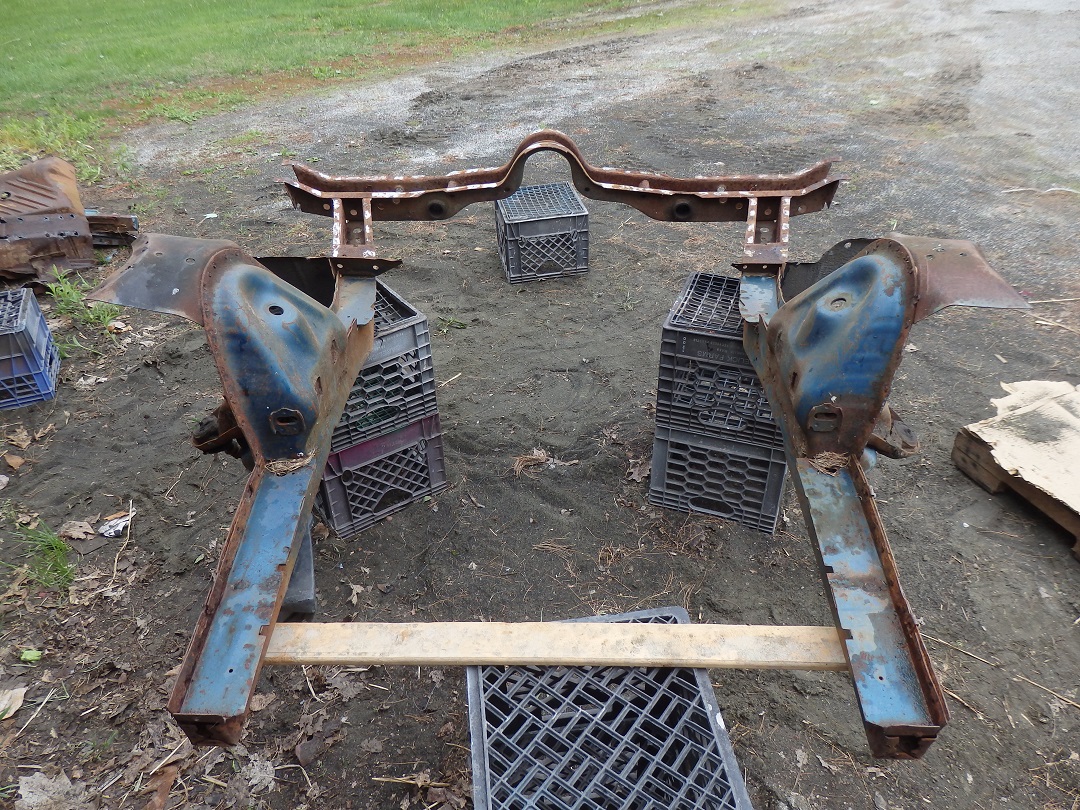
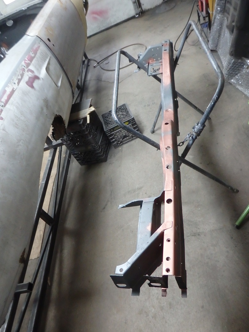
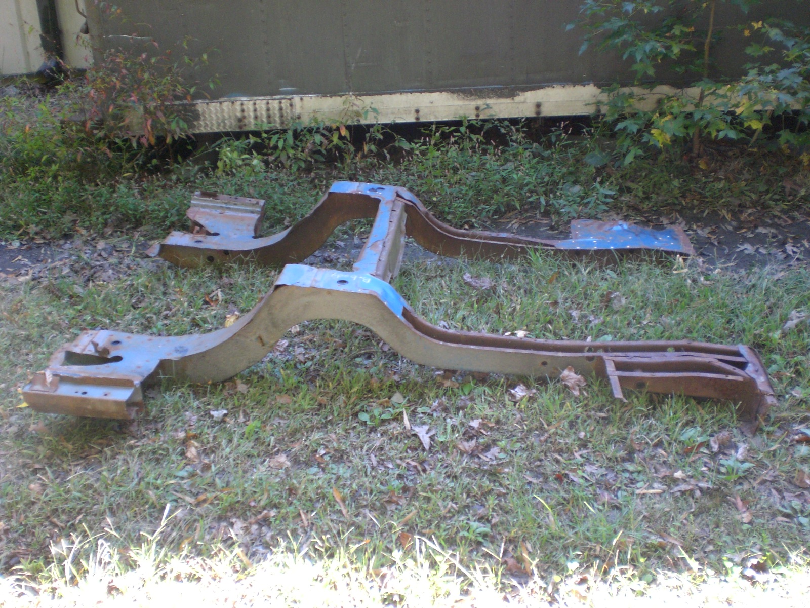 The rear frame rails did not come with the car. I bought them from Tony D'Agostino of Tony's parts. This is the picture he sent me before I bought them. He separated them and shipped them to me
all for a reasonable price.
The rear frame rails did not come with the car. I bought them from Tony D'Agostino of Tony's parts. This is the picture he sent me before I bought them. He separated them and shipped them to me
all for a reasonable price. |
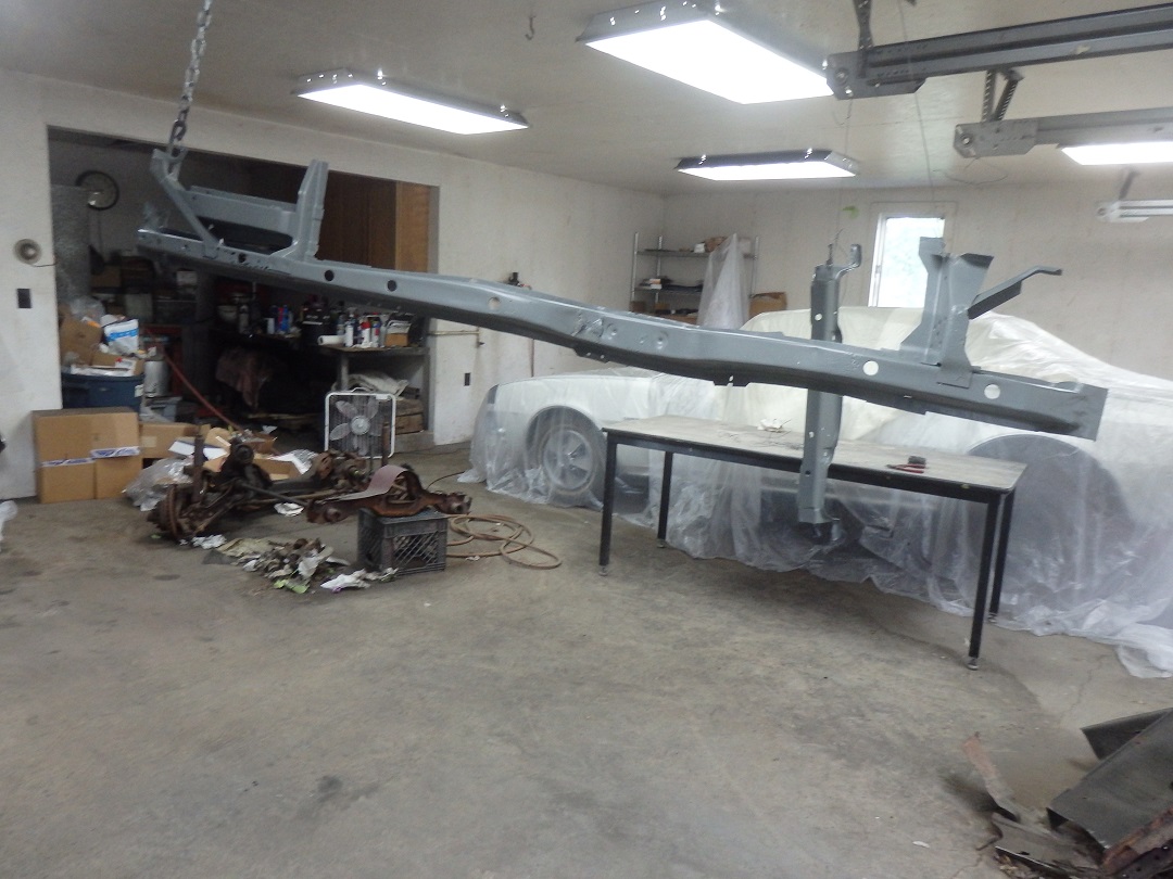 Once I got them, I cleaned them up and sent them to be sandblasted. They were then hung form the garage ceiling and put in epoxy primer.
 |
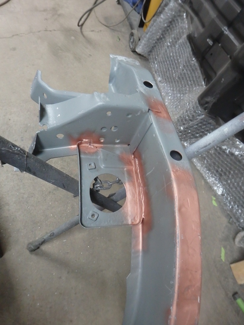
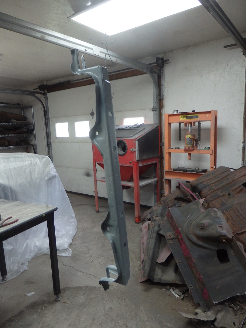 Here is the rear crossmember after priming.
 |
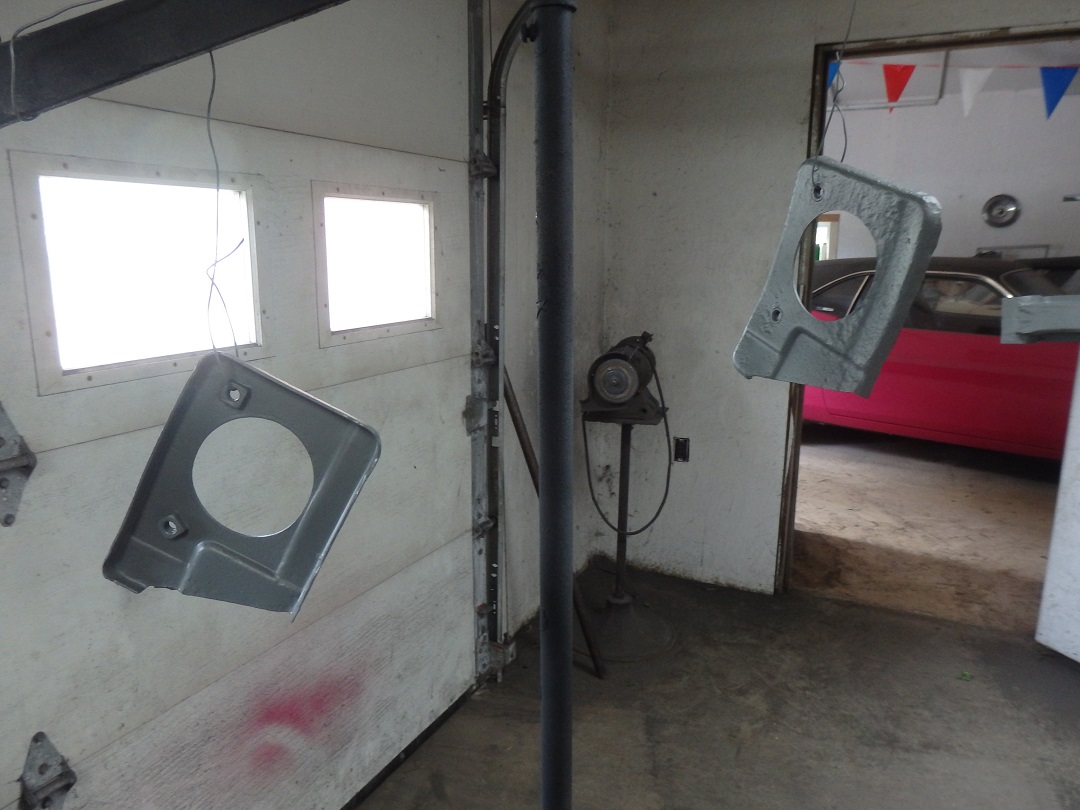 The rear seatbelt reinforcement plates were also sandblasted and primed.
 |
 The frame rails were not perfect, as was expected. I did have a few repairs to make.
 |
 Lastly the rear seatbelt reinforcement plates were welded to the frame rails. Note: Torque boxes get welled in much later in the process.
 |
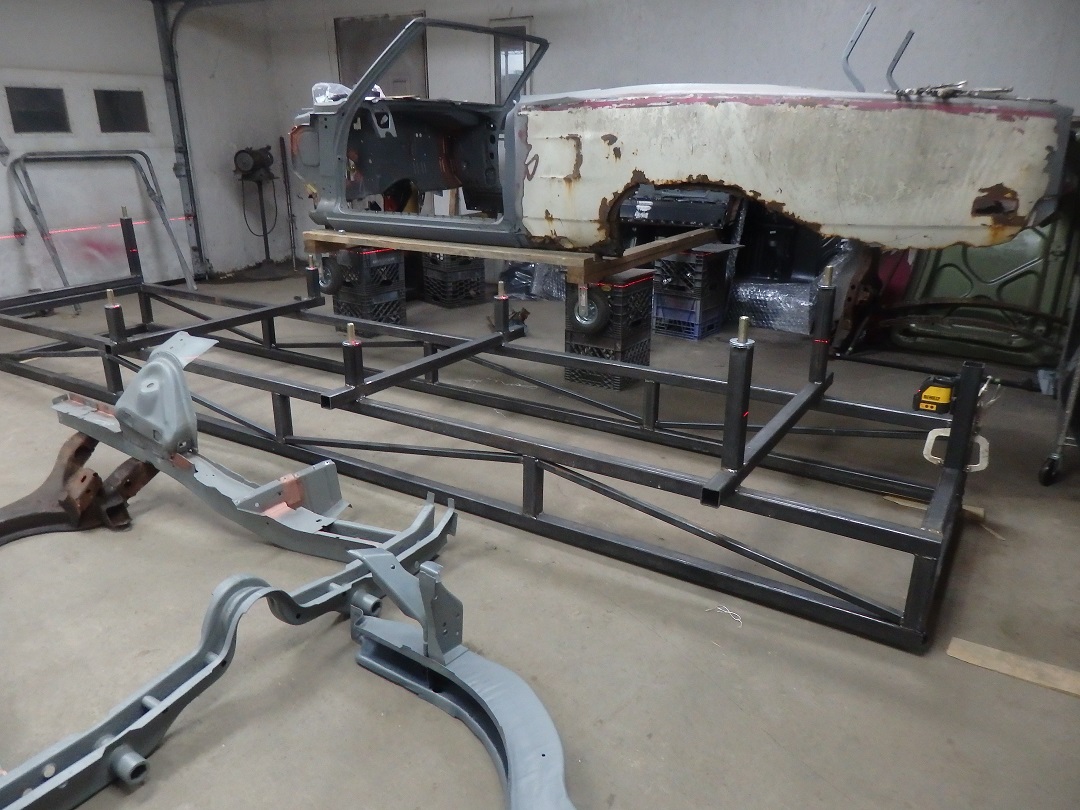
 I then started to build the jig. I started with making a box 12" high, 26" wide and 15 feet 6 inches long with crossbraces for reinforcements. I actaully welded it together
on a drive up car hoist as the deck was flat.
I then started to build the jig. I started with making a box 12" high, 26" wide and 15 feet 6 inches long with crossbraces for reinforcements. I actaully welded it together
on a drive up car hoist as the deck was flat. |
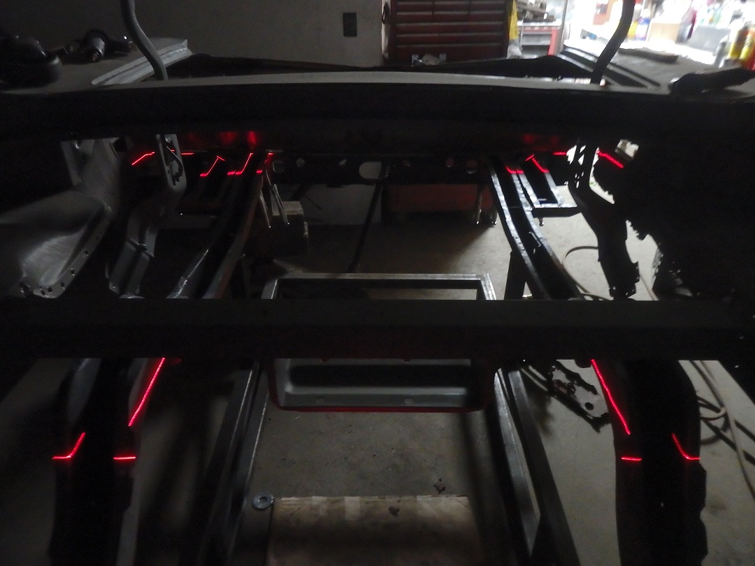
 I made a bunch of uprights using 1" bolts for pins to align to corresponding holes in the frame rails. I used a laser level and the frame rails to set the elevations and to make them level.
 In this picture you can see the red laser light contacting the edge of the washers on the center 4 uprights. Here's my trick. With the jig leveled on the floor, I fine tune the elevations by using ground down washers as shims. If you look at the left rear upright you will see an extra washer, which was needed to set the elevation correctly for that corner. |
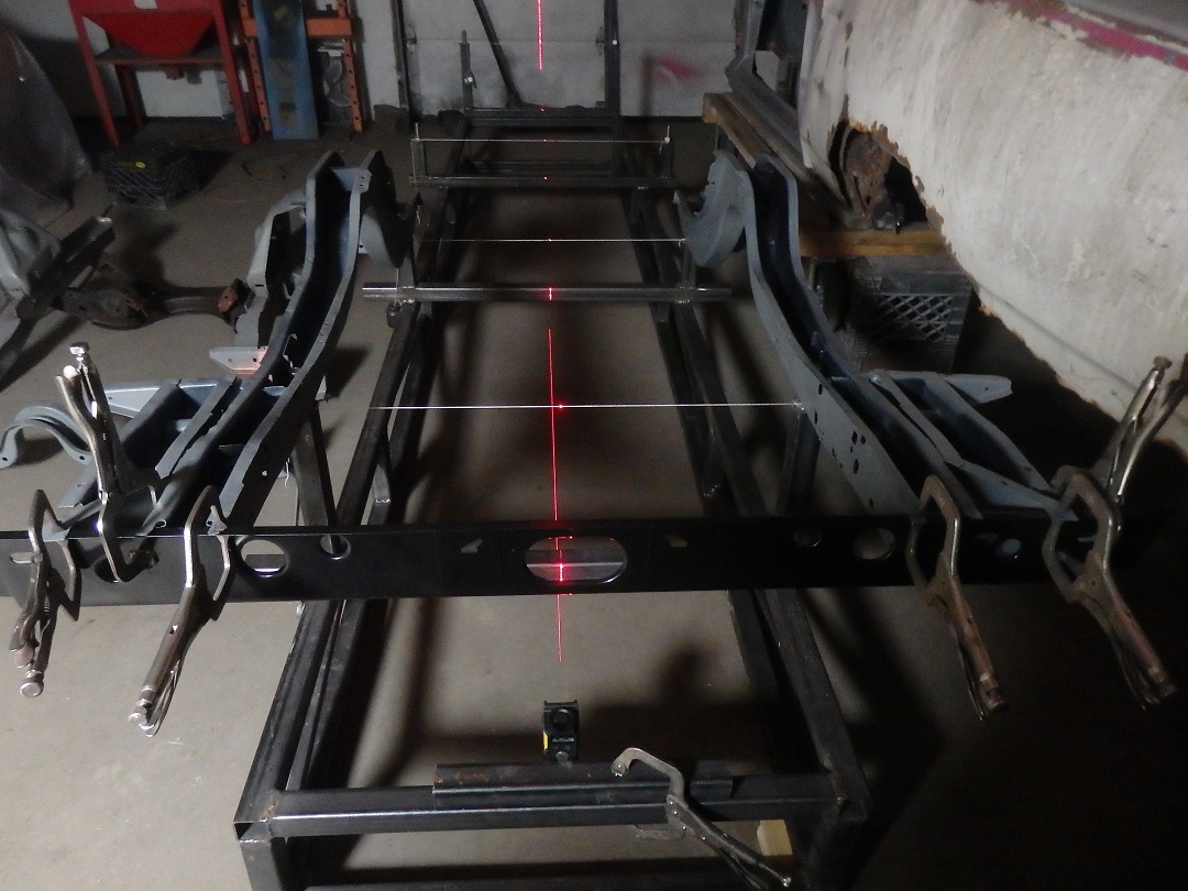 Pieces of string marking the centers were used to set the centerlines of each row using the laser level. Once the alignment was set, the uprights were welded to the base.
 |
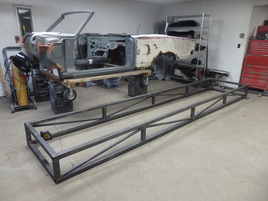
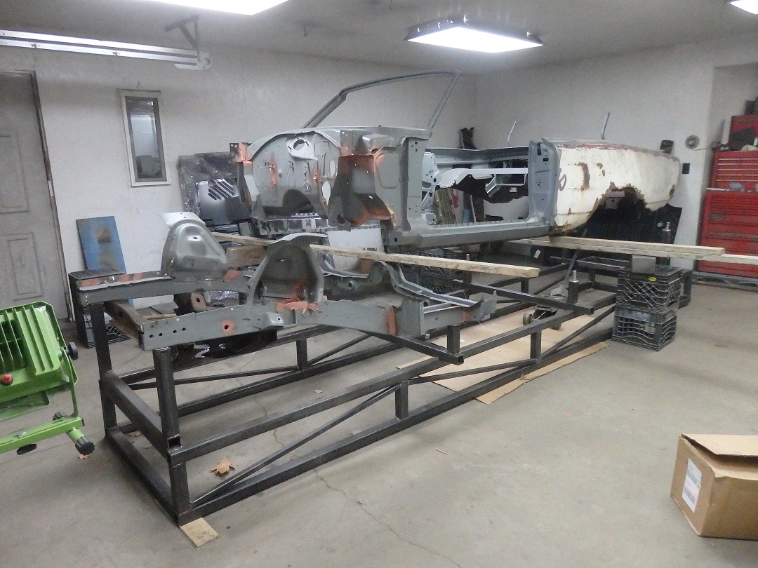
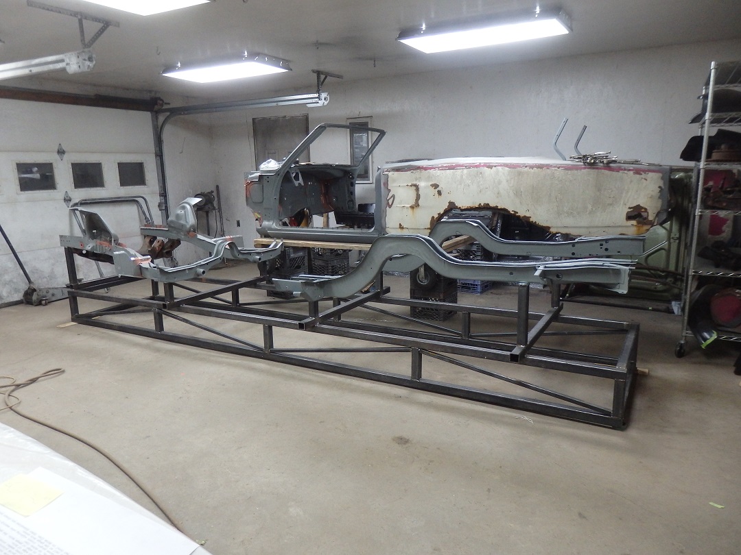 Here is the jig after it was completed. The frame rails were dropped in place and fit correctly. The K-frame was also installed to hold the front frame rails more rigidly.
 Who says you can't do a frame-off restoration on a unibody car ? |
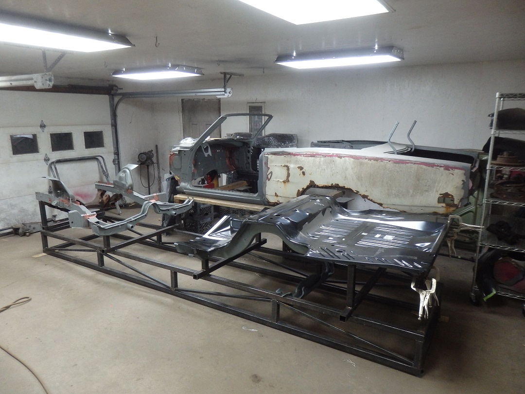 At this point I trial fitted and marked the holes to be drilled in the trunk pan and rear seat pan.
 |
 Now comes the fun. Aligning the body to the frame. This can't be done with the rear frame rails on the jig. And since I never separated the front crossmember from the front frame rails, the body had to be cocked
at and angle, left to right, because the inside face of the inner rocker panels are tapered in at the top.
Now comes the fun. Aligning the body to the frame. This can't be done with the rear frame rails on the jig. And since I never separated the front crossmember from the front frame rails, the body had to be cocked
at and angle, left to right, because the inside face of the inner rocker panels are tapered in at the top. |
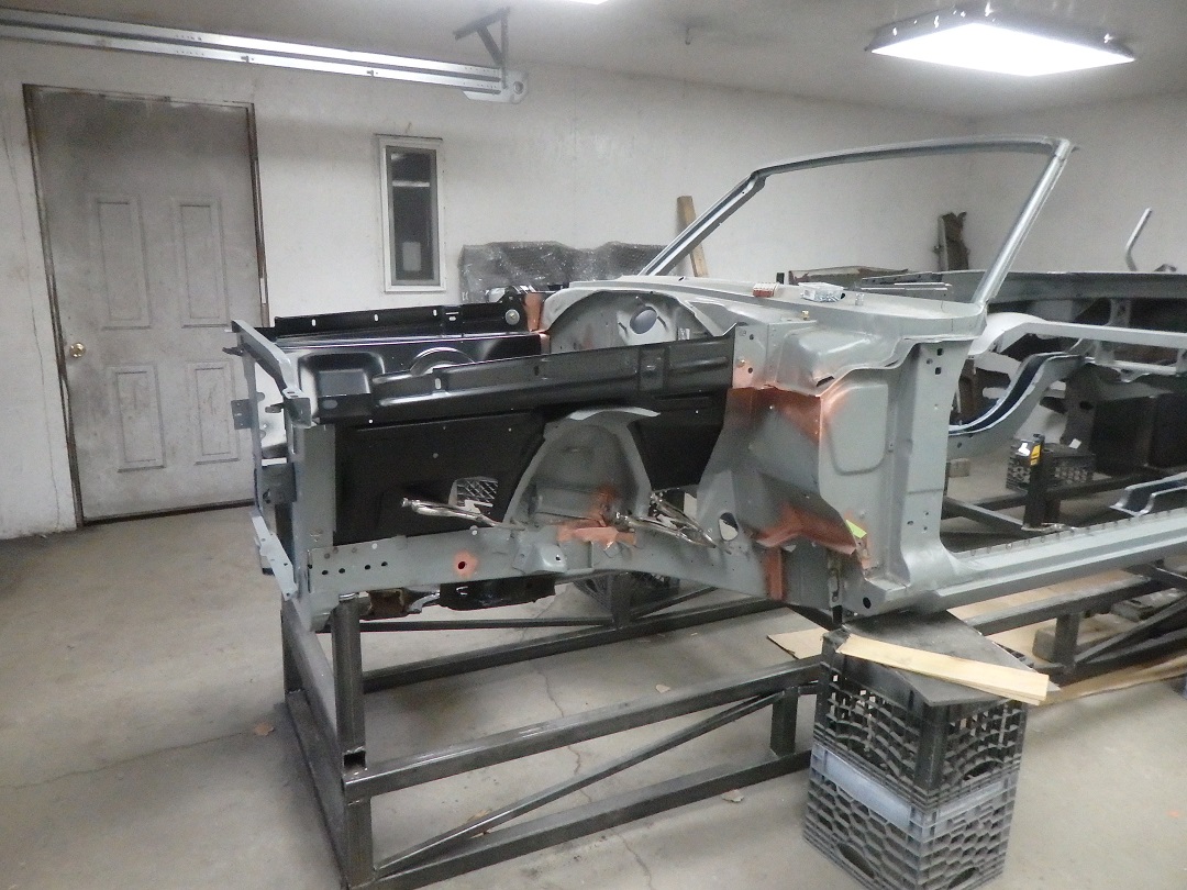
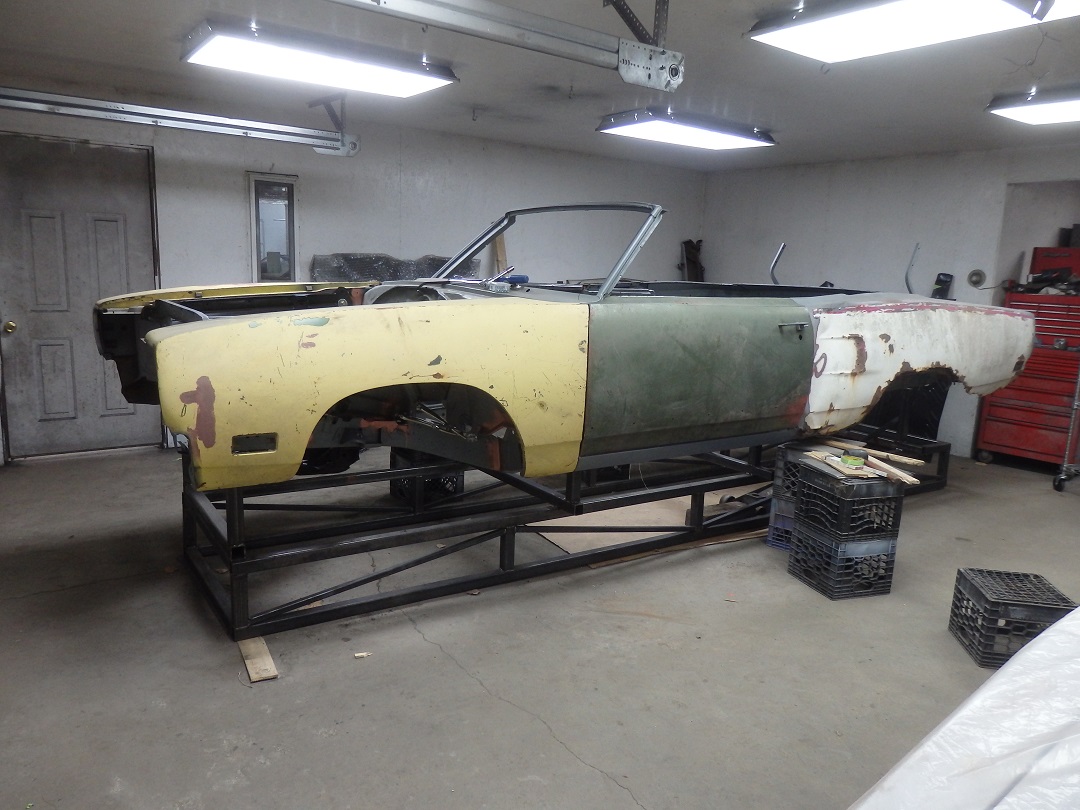
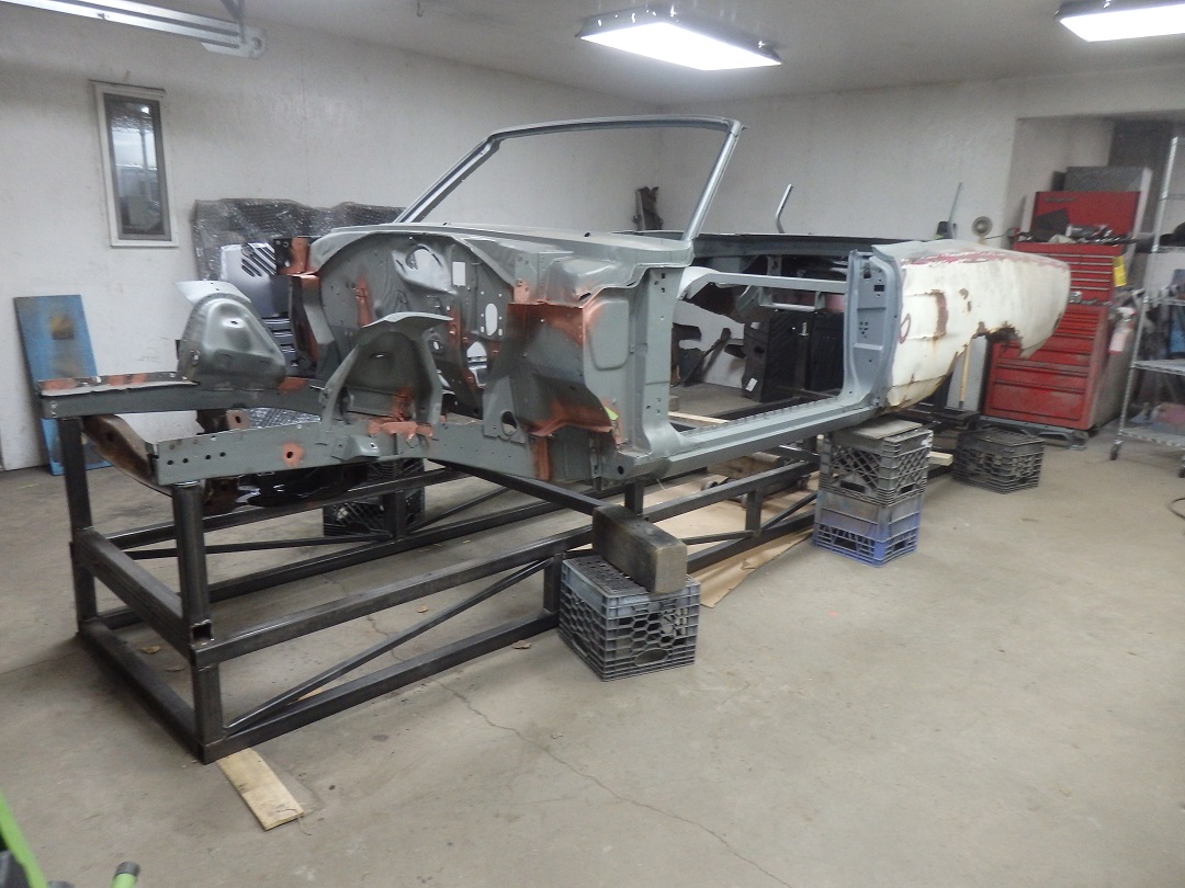 Here is the body positioned roughly correct at the front, but held up in the rear using milkcrates.
 |
 Then the rear frame rails were dropped in place. The rear crossmembers were then screwed to the frame rails.
 |
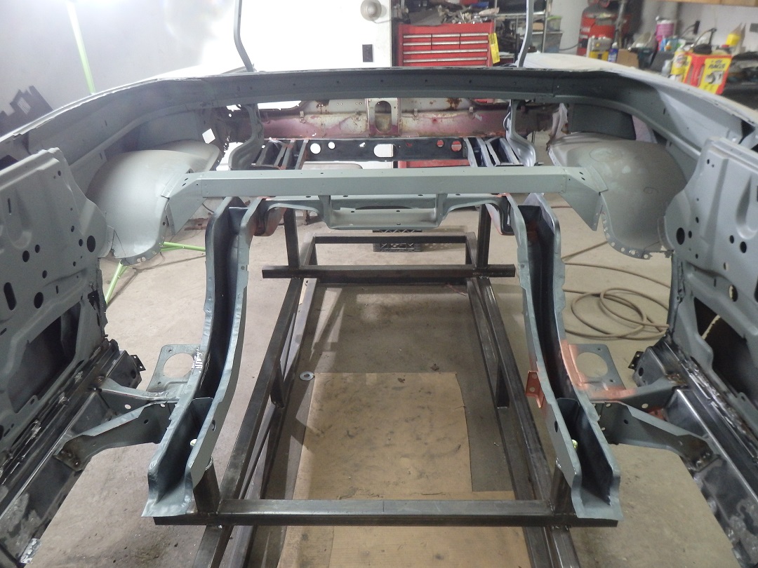
 Now things get tricky as there are no drawings to specify how high or low the body sets relative to the frame rails.
 I used a laser level to align the rear frame rails to the tail panel. |
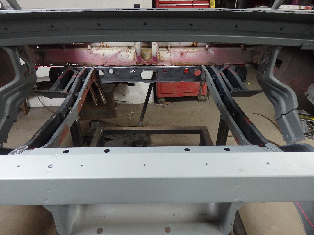
 Here you can see the laser alignment better.
 Of course I never took a picture, but I used the laser level to make sure the top of the inner rockers were level front to back and left to right. |
 Then everything gets screwed together.
 |
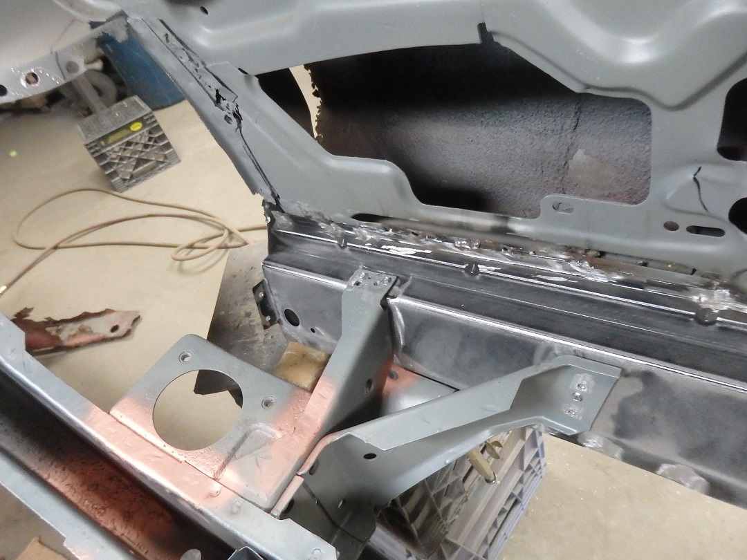
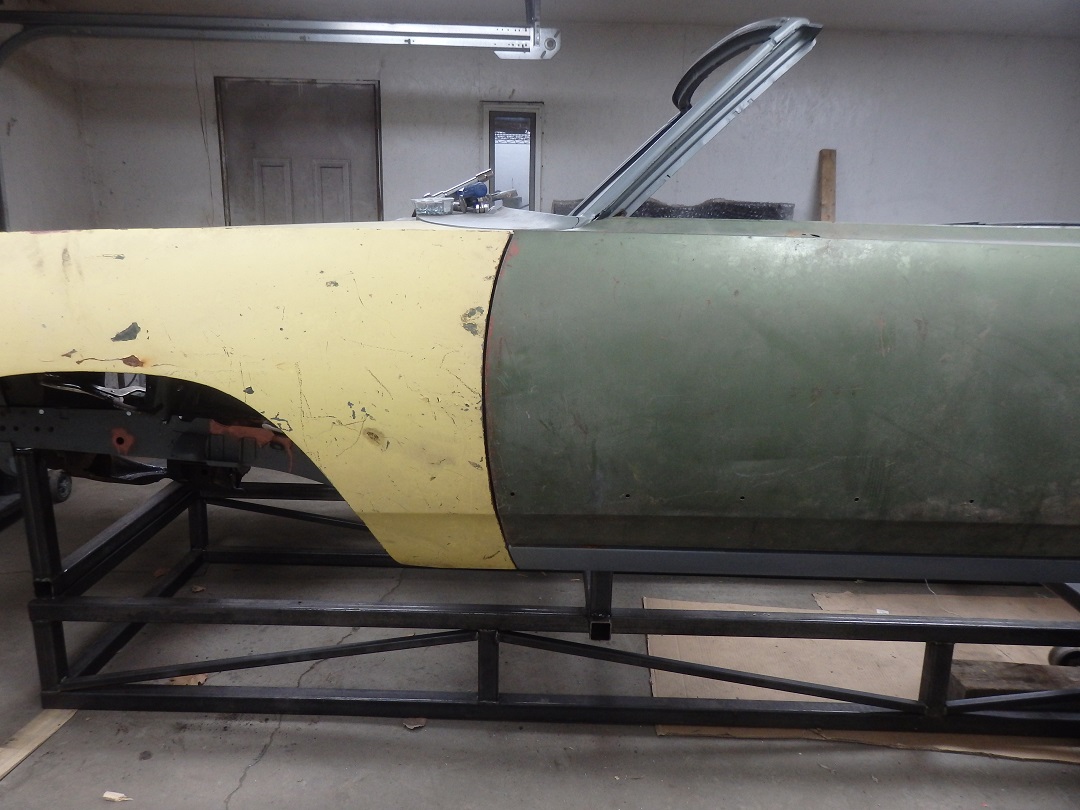
 I did fail to take pictures of the new inner rocker panels being installed before the body was brought down over the jig. So all I can offer is a glimpse of them in this picture and
the one above.
I did fail to take pictures of the new inner rocker panels being installed before the body was brought down over the jig. So all I can offer is a glimpse of them in this picture and
the one above. |
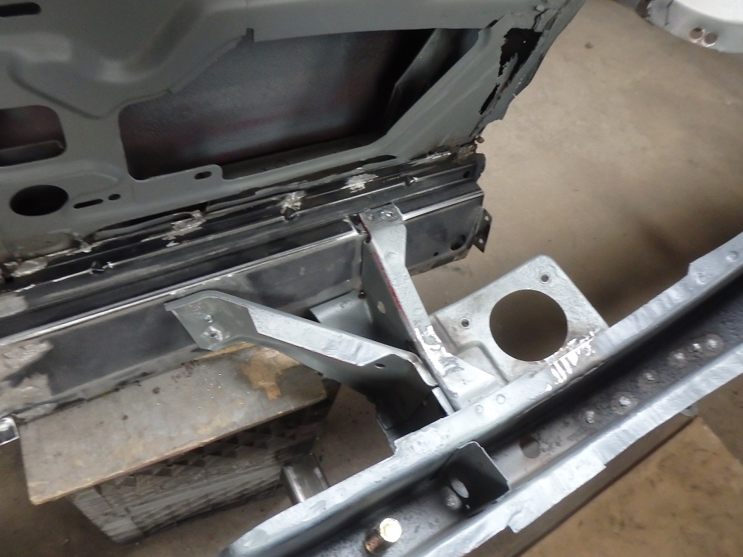
 Next up was to trial fit the new inner fenders and the radiator support.
 |
 The final alignment was done with the doors and fenders installed.
 |
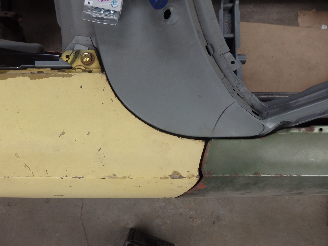
 The LH door and fender gaps were great.
 |
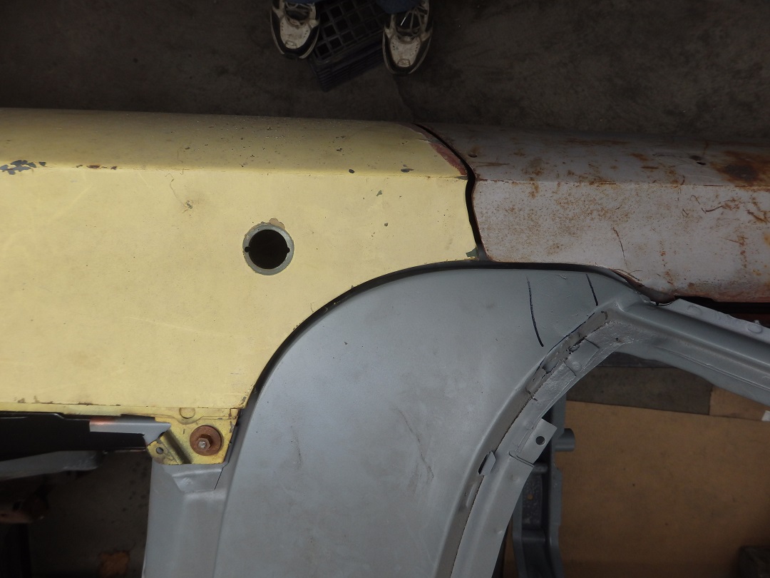
 In this picture the front of the LH fender could use to be brought out a little bit to give a better gap at the firewall, but otherwise looked pretty good.
 |
 The right side was spot on.
And with that, the frame rails were welded to the rocker panels. |