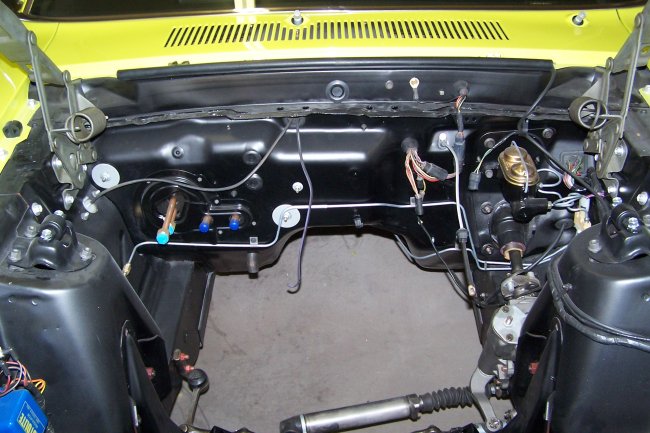
 Here is a typical firewall for an AC car. The factory put plugs in the holes used for the heater hoses and heater fan motor (orange) wire that was used on non-AC cars.
Ford used a special plug for the heater fan motor (orange) wire hole, which is not available as a repo. You have to use your old one or locate one.
Here is a typical firewall for an AC car. The factory put plugs in the holes used for the heater hoses and heater fan motor (orange) wire that was used on non-AC cars.
Ford used a special plug for the heater fan motor (orange) wire hole, which is not available as a repo. You have to use your old one or locate one. Missing in this picture is a retainer for the vacuum hoses that is supposed to go ontop of the firewall just above the previously discussed plugs. At the time of this writing (6/12/07) I am still trying to locate a used one. Every one that I have come across so far has been broken or rusted beyond use.
Just above the tranmission tunnel is a 'J-shaped' plastic clip. Its job is to hold the harness that goes to the transmission. This part is not reproduced and is very often missing.
 Here we have a shot showing the left side of the engine compartment. Notice that the service instructions decal is located on the fender apron and not on the shock tower. This
is because the car was built in Metuchen. Only cars built in Detroit or San Jose had these tags on the shock tower. You may also notice the 3 ribs in the left front fender apron.
Cars built prior to March 1969 did not have this ribbing. The actual date of the change over is not known, but it is around March 69 based on the examples that I have seen.
Here we have a shot showing the left side of the engine compartment. Notice that the service instructions decal is located on the fender apron and not on the shock tower. This
is because the car was built in Metuchen. Only cars built in Detroit or San Jose had these tags on the shock tower. You may also notice the 3 ribs in the left front fender apron.
Cars built prior to March 1969 did not have this ribbing. The actual date of the change over is not known, but it is around March 69 based on the examples that I have seen.Other things to note are the red nuts on the shock tower for the upper control arm and the red bolts holding the steering box in place.
 Here we have a shot showing the right side of the engine compartment. Notice that there is no hole in the fender apron above the battery box. The hole was added for the 1970 Model year, thought it
appears in NOS and repo fender aprons.
Here we have a shot showing the right side of the engine compartment. Notice that there is no hole in the fender apron above the battery box. The hole was added for the 1970 Model year, thought it
appears in NOS and repo fender aprons.The voltage regulator for this car was a yellow stamping. Only 1969 Mustangs built in San Jose w/o AC and w/o power top (conv only) had the silver stamping. Missing in this picture is a condesor that bolts to the bottom screw of the voltage regulator and gets plugged into the yellow wire. This was included in all cars equiped with a radio. Its job is to cut down noise heard in the speakers, which is created by the opening and closing of the voltage regulator contacts.
Located just below the voltage regulator is a plastic wire retainer. There should be two, but only one is installed in the picture. These are used to hold the main harness and alternator harness in place. I believe that the battery ground wire is routed through these retainers as well. Though the retainers are not reproduced, they are the same ones that are used under the dash behind the instrument cluster. So its easy to locate some prestine parts.
Other things to note are the red nuts on the shock tower for the upper control arm and the red bolts holding the idler arm in place.
 Here is a view you rarely see. The inside view of the radiator support without an engine installed. Though its not particularly interesting it does show the lower mounting brackets for the 24" radiator.
In this picture you can see the reproduced paint markings on the swaybar that are gold and pink. There are actually 3 markings here. The middle and right one go all the way around the bar. The left one is just a daub. I'm not really sure why the gold daub is there, but my other 302 fastback has the same markings. Remember, try to reproduce what you found and do not copy other cars.
 Here is a picture that shows the proper mounting of the AC expansion valve. The valve is attached to the lower line and the temperature probe is attached to the upper line.
 If you look closely enough you may notice that the heater hoses are different then on a non-AC car. The right hose is a regular heater hose, but with a 90 degree bend molded into it. This hose goes from the heater core directly to the water pump. The one to the left is a specially molded 'S-shaped' hose that goes to a vacuum control valve, which is just barely in the picture. The purpose of the valve is to keep the heater core from getting hot while running the AC.
 With all of the connections made, the expansion valve and the temperature probe are wrapped in a special insulation tape (Four Seasons Insulation Tape p/n: 59010). It is commonly refered to as 'monkey poop'.
I had to go to several parts stores before I was able to find one that could order it for me.
With all of the connections made, the expansion valve and the temperature probe are wrapped in a special insulation tape (Four Seasons Insulation Tape p/n: 59010). It is commonly refered to as 'monkey poop'.
I had to go to several parts stores before I was able to find one that could order it for me.In this picture you can see one of the rubber straps that hold the AC lines to the shock tower braces. There should be 4 in all. This is the same strap that holds the power steering lines together, just behind the power steering pump.