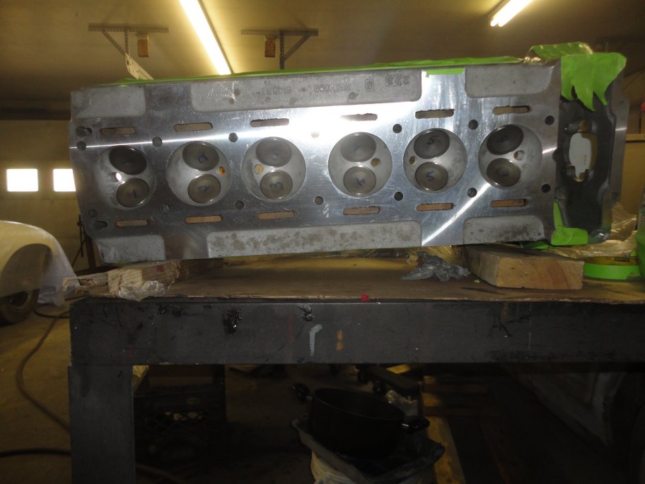
 1) Here is the head back from the machine shop. The work was done by Dale Spooner of Motion Machine in Danville, VA.
Dale has done lots of classic Jaguar heads. He was originally from Vermont, but moved to Virginia some time ago. He informed me that my head had been previously
worked on and that some valve guides had been replaced and one in particular was oversized by 0.005, but needed to be 0.006 since it was loose in the head. As
stated by Dale "A feeble attempt to make the guide larger was made by whacking it several times with a center punch had failed to make up the difference".
|
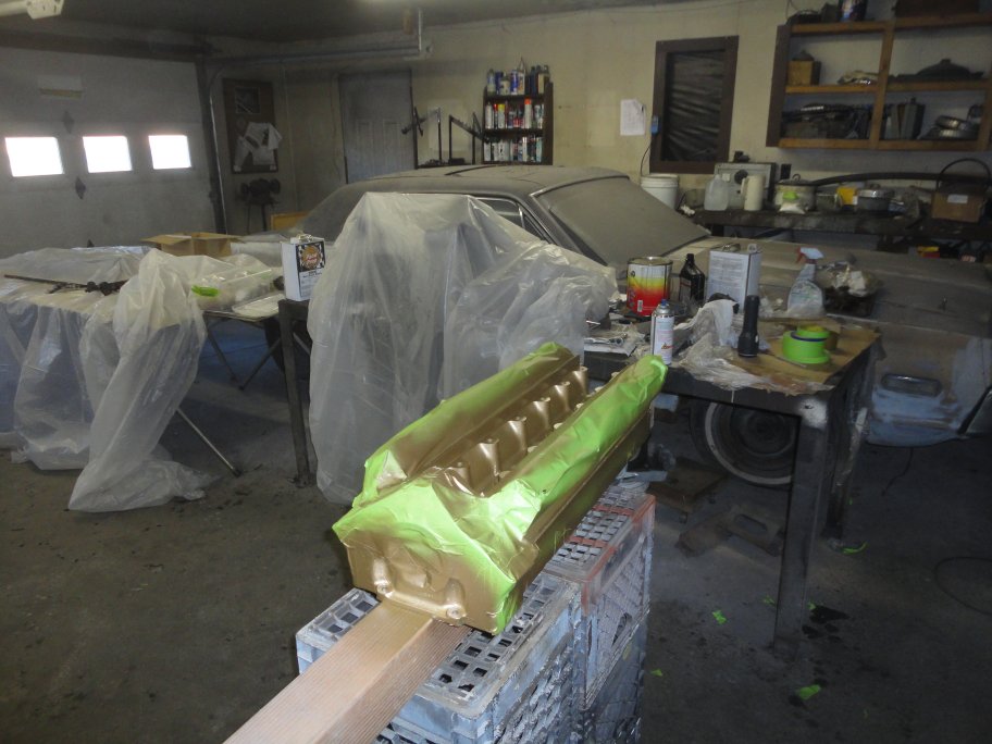 2) The first thing I did was polish the front of the head and paint it the correct gold color, which I bought from SNG Barratt.
|
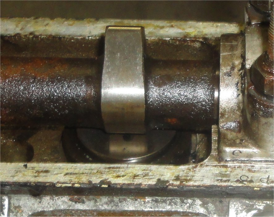 3) The next job was to set the valve clearance. Unfortunately I did not take any pictures of the process, so you are forced to look at some older pictures and
use your imagination.
The valve clearance is measured between the back side of the cam lobe and the tappet face. I bought new tappets since the old ones were not flat anymore. It is IMPORTANT to
note that only ONE cam can be installed in the head when performing this operation, since the intake and exhaust valves will collide and bend.
|
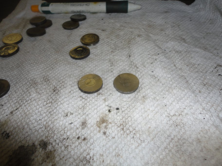 4) The clearance setting is recorded on the data plate rivetted to the RH inner sill. For the most part, the clearance is 0.004" for intake valves and 0.006" for exhaust valves. The clearance
is adjusted by replacing these shims. The clearance must be exact, so you must buy the correct one for each valve. In this picture you can see an old worn shim (worn pocket) and a new one.
Since I did not have any good original ones I had to estimate what I needed and bought 6 of them (3 0.105" and 3 0.106") which is enough to do one side. I used XKs Unlimited since they had tons of stock on each shim size.
They even have over and undersized ones that were never available from Jaguar.
This took me several purchasing cycles. When I determined what I needed for shims the first time, I found that I was off 0.001" on a couple of my measurements, so I had to buy some more. I'm not quite sure
what went wrong since I made sure that I always used the tappet on each valve and I always torqued the cam down.
|
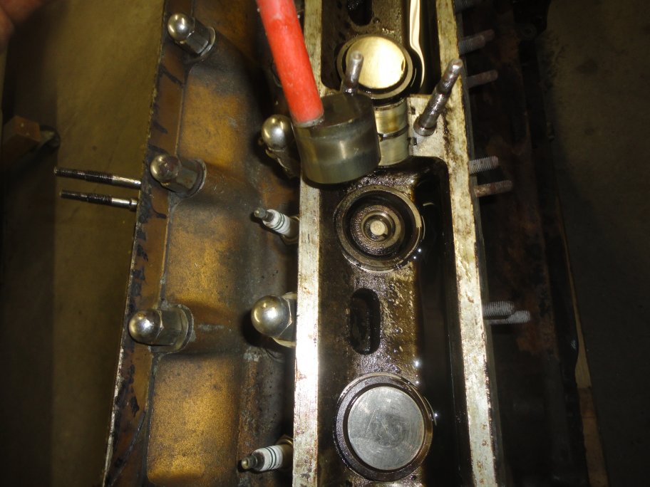 5) Here is a picture showing a tappet being removed using a magnet. The shim is stuck to the underside of the tappet on this one. The guides for the tappet weren't worn enough to need replacing so I did not have them
replaced. I also did not have the machine shop install a stakedown kit. A stakedown kit is comprised of a set of brackets and screws which are intended to hold down the exhaust tappet guides. This is a typical
problem experienced with exhaust tappet guides. The heat causes the aluminum head to increase in size and the tappet guides can loosen up. If you are intending to race your Jaguar, you should spend the money
and get a stakedown kit installed. It is not very expensive and all the machine shop needs to do is drill and tap a few holes into the aluminum head.
|
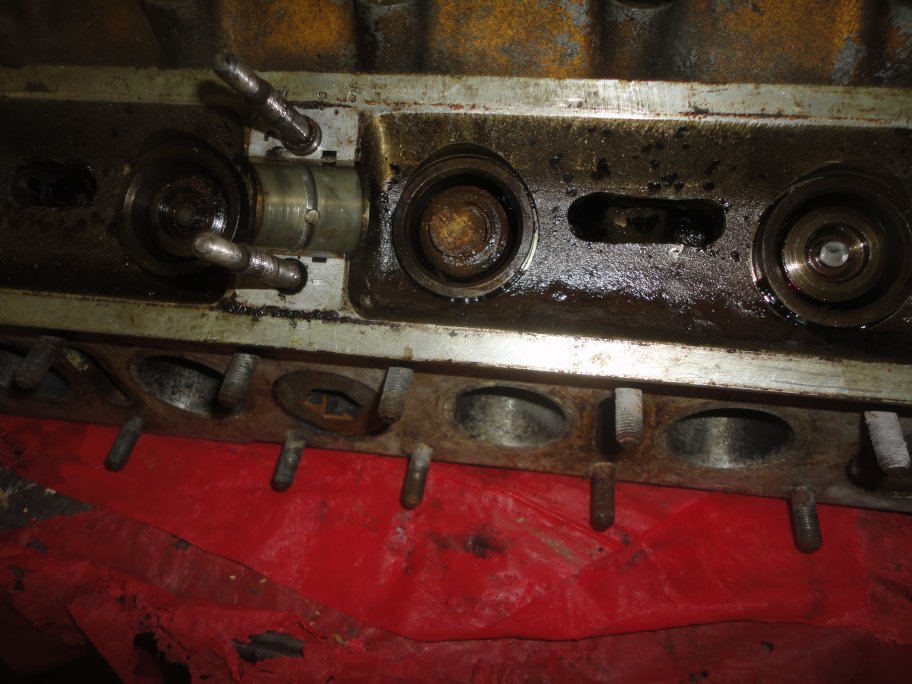 6) This picture shows an original shim in place on top of the valve stem. As you can see, it is quite the pain to set the valve clearance by replacing shims. You have to removed the cam and the tappet to swap out shims. When you are all done on one side, you have to removed the cam again to do the other side.
|
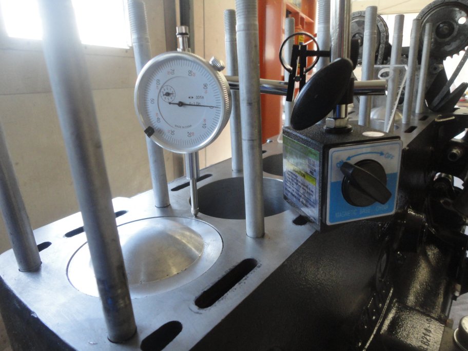 7) If more than perhaps 0.020" has been removed from the head and the block since the engine left the factory you may want to consider measuring the compression ratio to determine if you need a thicker than standard head gasket. The process to do this has been documented by Ray Livingston and he will be more than happy to e-mail you his instructions and spreadsheet so that you can do this yourself. I won't steal his glory here. I just visually documented the measurements I took so that others may have an easier time following his instructions.
The first thing that needs to be done is the dial indicator needs to be setup and zeroed on the deck.
|
 8) The dial indicator needs to be rotated over a piston (any piston) and the piston needs to be brought to the very top of its bore. This is actually pretty easy to accomplish.
|
|
|
|
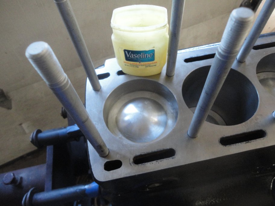 9) The piston needs to be lowered exactly an inch down. The dial indicator can then be removed.
Since mineral spirits will be poured into the bore, the cylinder needs to be sealed around the piston to keep the mineral spirits from leaking past.
|
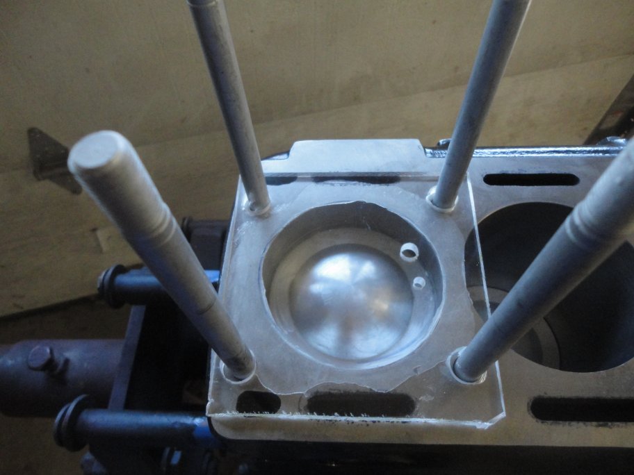 10) A lid is made out of plexiglass with a fill hole and vent hole. The lid is sealed around its perimeter with grease or in my case vaseline.
|
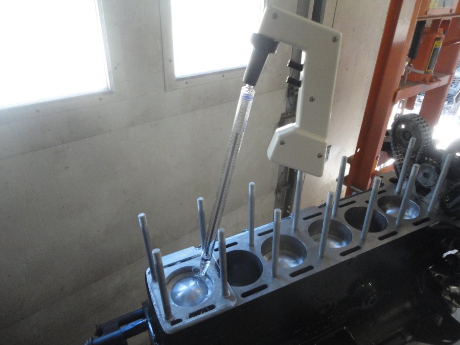 11) Mineral spirits are used to fill the void between the piston and lid. You must measure the exact amount used. Ray recommends a burrette. Since I couldn't locate one, I used a hand-held pipette. I filled the cylinder 3 times to make sure I got a good number.
|
 12) You must also measure the void in the head. Ray recommend using a wooden dowl to fill the sparkplug hole, buy I opted for an actual sparkplug. You should make sure that both valves are closed or else the mineral spirits will leak out.
|
 13) My compression ratio calculated out to be 9.27:1 so I was able to stick with an original style head gasket. It is recommended that a sealer be used with the original style gasket. I used Permatex High Tack. It is sprayed onto the gasket and has a copper color as seen here.
|
 14) Dropping the head in place is relatively simple. I was able to do this alone. The timing gears tended to want to hang up on the inside of the head, but I was able to wiggle them trough the opening.
There are a few things that I need to mention about the earlier 3.8L engines. They did not come with chrome engine lift hooks. The head is located with a special dowl head stud, but on engines without the lift hooks dowl the head stud is shorter (about 0.5" shorter). If you replace the headstuds you must get the correct shorter dowl head stud.
Also even though you can buy a new set of chrome dome nuts and chrome D-washers, nobody carries the original style round washers that are used on the earlier engines. This pictures shows the original round washers and their correct locations. The 2 in the middle are there for the spark plug wire duct mounting locations.
|
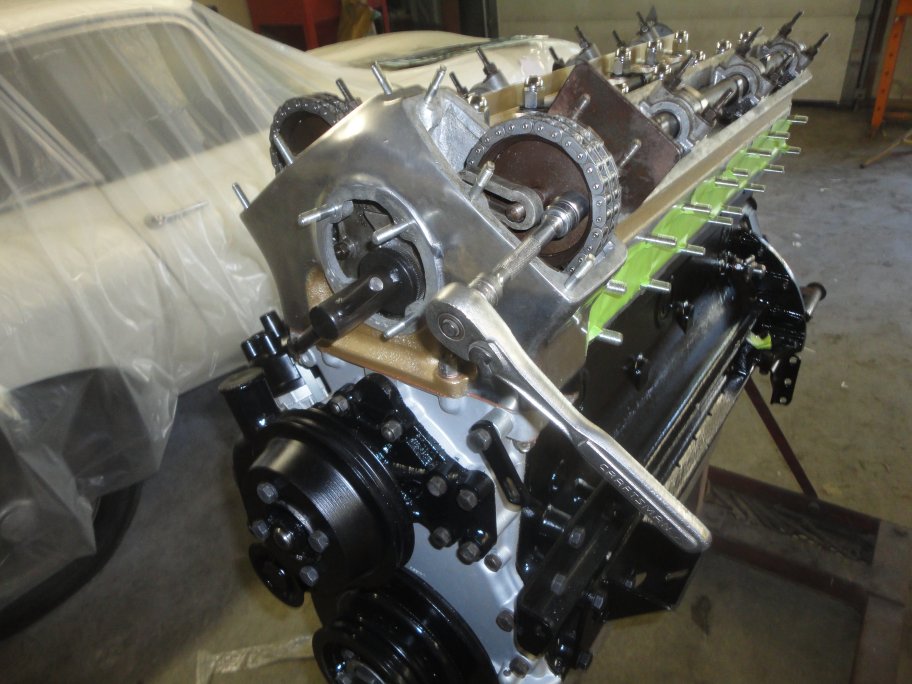 15) Once the head is properly torqued down, the cam timing gears need to be attached to the cams and the timing chain needs to be properly tensioned. Special tools are required for this. Luckily they only cost $20 ea. The cam key tool original came in the tool kit that was supplied with every car. Its job is to hold the cam in place while the timing chain is attached. The cam tool is seen in position in this picture.
Here is a brief overview of the timing gear setting procedure. First of all the came gears need to be seperated. A cam gear is actually comprised of 2 parts. An inner disk with teeth and the outer gear which has teeth along the inside as well as the outside. The 2 parts are held together with a wire clip. With the cam tool holding the cam in place, the outer portion of the gear is placed over the end face of the cam. The inner disk piece is rotated (while it is not connected to the outer piece) so that the bolt holes line up with the threaded holes in the cam face. Then the inner disk is inserted into the outer gear. Sometimes you may have to rotate the inner disk 180 degrees to get the teeth to mesh. Then the gear is bolted to the came and the wire clip is then inserted. The process is repeated for the other cam.
With the cams set, the timing chain tension needs to be set. This is done with a special tool (seen here). This tool never cam with in the tool kits. The tension is set by bushing a spring-loaded button in while simultaniously rotating the tool. The service manual just says that there should be a little slop in the chain on either cam gear. You have to rotate the engine to check the slop and in my case I had to reset one of the cam gears.
|
 16) The last step is to run the locking wire through the cam bolts.
|
|